PLC Communication
PLC Communication or PLC Integration refers to the exchange of data between programmable logic controllers (PLCs) and other devices. It is an industrial-grade digital computer designed for control functions in various industries. It replaces older technologies like electromechanical relay systems. PLCs are modular, allowing users to add features like discrete and analog inputs/outputs, PID control, motor control, and more. One of the advantages of using the PLC is they are easier to troubleshoot, maintain, and cost-effective compared to relay banks.
How Can a Scale Help with PLC Applications?
Our weighing scales play a crucial and significant role in enhancing PLC applications in several ways. Weighing scales integrated with PLCs can provide precise measurement at high speeds, which is essential to many industrial processes.
Analog Output 4-20 mA, 0-5 VDC, 1-5 VDC
Analog output utilizes signals such as 4-20mA, 0-5V, or 1-5V to send weight data from a scale to a PLC (Programmable Logic Controller). These signals represent the weight as a continuous electrical value that the PLC can process. For example, in a 4-20mA system, 4mA might correspond to zero weight, and 20mA to the full capacity of the scale. To ensure compatibility, it’s essential to confirm the PLC’s analog input card supports the chosen signal type and power configuration—whether it’s line-powered, loop-powered, or self-powered. This determines how the devices interact electrically.
For more information on the differences of each of these signal types and various other documentation, visit the Wiring Diagrams section in User Manuals and Specifications page.
Once connected, the PLC reads the analog signal and translates it into weight data for automated control. Proper calibration of the PLC to the analog signal range is critical for accuracy. Calibration ensures the PLC interprets the signal correctly, such as mapping 4mA to the scale’s zero point and 20mA to its maximum capacity. This setup is widely used for applications like controlling material flow, monitoring hoppers and silos, and sorting based on weight thresholds.
These systems are common in manufacturing, agriculture, and logistics for tasks like batching, mixing, and valve control. Analog outputs are reliable and effective, but careful attention to compatibility, power configurations, and calibration is essential for accurate and efficient integration into automated processes
Arlyn Scales supports all kinds of analog output configurations. Contact us for more details.
Serial Communication / RS-232 / RS-422 / RS-485
Serial communication, such as RS-232, RS-422 and RS-485 allows weighing scales to connect to PLCs (Programmable Logic Controllers) for seamless data transfer. The scale sends weight data as digital signals through a serial connection, typically using transmit (TX), receive (RX), and ground (GND) wires. The PLC is configured with matching communication settings, like baud rate and data format, to accurately interpret the incoming data.
Once integrated, the PLC uses this weight data to automate processes. For example, it can stop a conveyor belt when a target weight is reached, control batching and mixing systems, or reject items that don’t meet weight specifications. The data can be sent continuously or on-demand, depending on the application.
This setup is widely used in industries like manufacturing, packaging, and logistics. Common applications include inventory management, quality control, and automated filling systems. While RS-232 is reliable and straightforward, newer technologies like Ethernet or wireless communication are sometimes used for more advanced operations.
RS-232 and other serial communications are offered on most Arlyn Scales. Press the “Configure and Buy” button on any scale page and select “RS-232 Communication” in the Outputs panel.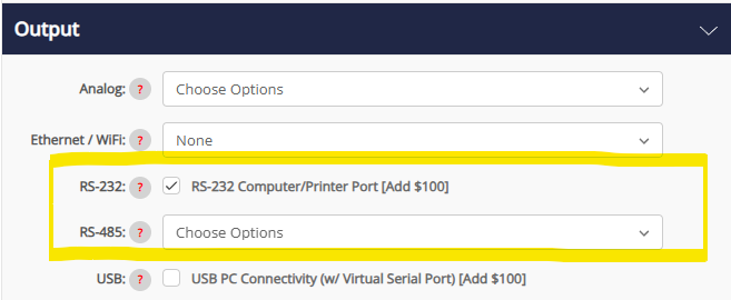
MODBUS TCP and MODBUS RTU/ASCII
Scales can be integrated with a PLC using MODBUS protocols such as MODBUS RTU/ASCII and MODBUS TCP, enabling efficient and precise data exchange. MODBUS RTU and ASCII are serial communication protocols, typically using RS-485 or RS-232 connections, while MODBUS TCP operates over Ethernet networks, offering faster speeds and easier connectivity to modern systems. This allows scales to send detailed weight data and status information directly to the PLC for processing.
MODBUS integration is widely used in applications like inventory management, automated packaging, and quality assurance. For instance, in logistics, a scale can send real-time weight data to a PLC for load monitoring in shipping or receiving. In industrial settings, MODBUS-connected scales help track material usage, manage storage silos, or monitor manufacturing throughput. Unlike traditional batching and mixing systems, these applications often involve more advanced data logging and system-wide process optimization.
Choice between MODBUS RTU vs. MODBUS TCP
The choice between MODBUS RTU/ASCII and MODBUS TCP depends on the system’s requirements. MODBUS RTU/ASCII requires a direct serial connection and is ideal for small-scale or localized systems. In contrast, Modbus TCP leverages Ethernet, supporting multiple devices over a network, easier scalability, and remote access. For optimal integration, ensure the scale and PLC support the same Modbus version and configure addresses and communication parameters correctly for seamless operation.
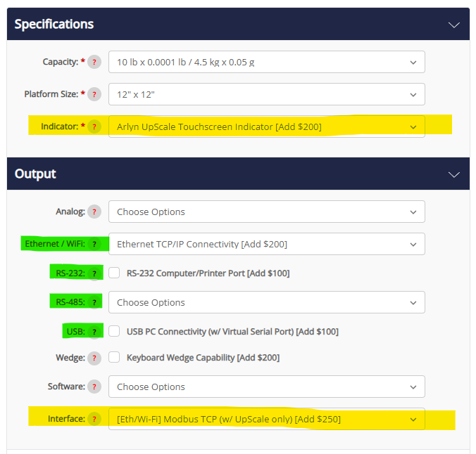
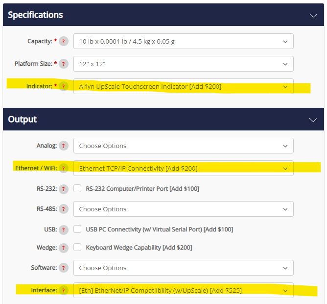
Arlyn Scales offers MODBUS communication on any scale equipped with the Arlyn UpScale Touchscreen Indicator (also available as a configurable option on the “Configure and Buy” page on any scale). On the “Configure and Buy” page on the scale:
- On the “Specifications” panel, select the Arlyn UpScale Touchscreen Display for the indicator.
- On the “Output” panel, select a digital output option such as RS-232, Ethernet or Wi-Fi, RS-485 or USB.
- Then drop down the “Interfaces” options and select a MODBUS communication (TCP or RTU/ASCII) depending on your output selection.
For more information on how our scales work with MODBUS communication, see MODBUS Addendum PDF in the MODBUS Utilities section.
EtherNet/IP
EtherNet/IP also known as Ethernet Industrial Protocol is a popular industrial network protocol that allows for high-speed data transfer and efficient exchange of critical control data across devices and systems . It is used in PLC communication systems and offers several advantages such as High-Speed data transfer, consistent communication, support of various devices, integration with other protocols, explicit and I/O messaging.
Arlyn Scales offers scales that can be integrated with a PLC using EtherNet/IP, a powerful industrial communication protocol designed for seamless data exchange. EtherNet/IP enables direct, high-speed communication between the scale and the PLC over a standard Ethernet network. Unlike traditional protocols, EtherNet/IP uses Common Industrial Protocol (CIP) to ensure real-time, synchronized data sharing, making it ideal for complex industrial systems requiring high reliability and scalability.
Integration using EtherNet/IP is widely applied in industries such as logistics, quality assurance, and inventory management. For example, Arlyn Scales can monitor tank levels in real-time to prevent overfills, measure loads for freight shipping, or track materials in large warehouses. These applications often demand precise weight data and advanced analytics, going beyond basic batching or conveyor operations to provide insights for optimizing processes and improving productivity.
Differences between EtherNet/IP and Ethernet TCP/IP
EtherNet/IP differs from Ethernet TCP/IP with socket and Telnet ASCII communication in both functionality and purpose. TCP/IP with Telnet or socket communication is a general-purpose protocol suited for simple, command-based communication, while EtherNet/IP is tailored for industrial environments, offering pre-configured data structures and real-time performance. EtherNet/IP requires devices to support CIP and conform to its specifications, such as proper addressing and synchronization settings. Its advantages include faster setup, robust data integrity, and compatibility with large-scale industrial automation systems, making it a superior choice for complex operations.
PROFINET
Arlyn Scales can be integrated with a PLC using PROFINET, a modern industrial Ethernet protocol designed for high-speed, real-time communication. PROFINET allows scales to send precise weight data to PLCs seamlessly, enabling efficient control of automated processes. This protocol supports advanced features like device diagnostics, easy scalability, and compatibility with existing Ethernet networks, making it an ideal solution for complex industrial environments. Integration is straightforward, as PROFINET-equipped scales connect directly to the PLC using Ethernet cables, eliminating the need for legacy connectors.
PROFINET is widely used in industries like logistics, food processing, and manufacturing for applications such as inventory tracking, quality assurance, and material monitoring. For example, Arlyn Scales can provide real-time weight data for managing tank levels, automating sorting systems, or monitoring raw material usage during production. These applications require reliable and continuous data transfer, making PROFINET’s fast response times and robust communication capabilities a perfect match.
Comparison between PROFINET and PROFIBUS
Compared to PROFIBUS, an older serial protocol, PROFINET offers faster data transfer rates, greater flexibility, and simpler connectivity. While PROFIBUS relies on dedicated cabling and is suitable for legacy systems, PROFINET operates over standard Ethernet infrastructure, reducing installation costs and supporting higher device counts. PROFINET also requires specific settings, including proper IP configuration, real-time clock synchronization, and compatible PLC hardware and firmware. Its ability to handle high data volumes with minimal latency makes PROFINET the superior choice for modern automation systems.
The Right Choice of Communication for Scale Integration with a PLC
With each of the methods for the scales communicating with the PLC, all of them will vary depending on the PLC model, software, and network you are using. Always refer the the user manual or contact the manufacturer’s customer support for model-specific instructions.
