Intrinsically Safe Ultra Precision Scales – ArlynGuard S
INTRODUCTION
Congratulations on your purchase of the Intrinsically Safe Ultra Precision Scale – ArlynGuard S. This Scale offers a combination of versatility, accuracy and simplicity in an easy to use and easy to maintain package. Advanced menu driven operating software, large memory capacity and an easy to use menu structure allows the scale to be configured for almost any application. To obtain the best performance and greatest utilization from your scale, read this instruction booklet completely and carefully.
SCALE VERSION
The firmware version is shown when the scale is booted up. The version number can be seen at the bottom right of the screen during the logo splash. The firmware version can also be checked by pressing the MENU button -> SETUP MENU -> SYSTEM SETUP -> VIEW VERSION NUMBER.
FEATURES
| Easy to read, LCD Graphics display | Intrinsically Safe SAW Load Cell |
| Automatic Calibration | Computerized Self Testing |
| Multiple Tare Weights | Automatic Zero Tracking |
| No Moving Parts | Full Text and Floating-Point Entry |
| Large Memory Capacity | On Line Help |
| Eight Unit Conversions Standard | Optional Weight Average Function |
| High Accuracy Parts Counting on Many Models | Optional Windows Interface Software |
| Automatic or Numeric Entry Tare | Optional Setpoints |
| Sealed “Click-Type” Control Panel |
PRECAUTIONS
- Prevent inflammables and liquids from entering scale head.
- Allow clearance on all sides of scale platform for accurate weighing.
- Do not drop large loads on scale platform.
- NEVER EXCEED THE RATED CAPACITY OF THE SCALE.
- Do not pull on the connecting electrical cables.
- Make sure that the scale and ramps are properly secured to the floor (most models).
BEST CONDITIONS FOR WEIGHING
- The scale should be level.
- Best operating temperature is about 68 degrees F.
- The weighing area should be kept clean and dry.
- The surface that the scale is resting on should be of solid construction and not prone to vibrations.
- Don’t install the scale near heater or air conditioner vents.
- Avoid drafts.
- When connecting the scale to an AC power using a Safety Barrier, please utilize a stable AC power supply. Avoid heavy motorized equipment on the same power line.
- Do not operate the scale in close proximity of RF transmitters like cell phones and walkie-talkies.
- Warm-up the scale before use.
THIS MANUAL
This instruction manual (DOC4500) covers the installation and operation of the MKE-5-IS Intrinsically Safe Scale Indicator. Indicated below are the manual’s current revision number and number of pages. Please check this manual and its control drawings for missing pages. The installation cannot continue unless all pages are present.
| Instruction Manual DOC4501 | MKE-5-IS SAW Instruction Manual | 40 Pages |
| Control Drawing DOC4010 | MKE-5-IS General Dimensions | 1 Sheet |
| Control Drawing DOC4011 | MKE-5-IS Indicator Label Drawing | 1 Sheet |
| Control Drawing #4013 | MKE-5-IS Inst. and Wiring Diagram | 7 Sheets |
| Control Drawing #7213 | Approved SAW-IS Body Type SAW-LC-08215, Label Drawing | 1 Sheet |
| Control Drawing #7214 | Approved SAW-IS Body Type SAW-LC-16033, Label Drawing | 1 Sheet |
| Control Drawing #7334 | Approved SAW Load Cells Installation and Wiring Diagram | 2 Sheets |
FACTORY MUTUAL APPROVAL AND INTRINSIC SAFETY
 |
The MKE-5-IS SAW Scale System has been rated intrinsically safe by Factory Mutual only when used with specific intrinsically safe Arlyn load cells and the installation is performed by a qualified technician who conforms to the guidelines described in this manual. Consult the chapter titled “Installation and Wiring” along with the control drawings in the back of this document for information pertaining to the installation and wiring of the approved strain gage Load Cells. |
MKE-5-IS (A). DIGITAL WEIGHT INDICATOR SYSTEM
Intrinsically Safe for use in Class I, II and III, Division 1, Groups A, B, C, D, E, F and G; Temperature Class T3C Tamb = -25°C to +40°C; Temperature Class T3B Tamb = -25°C to +60°C in accordance with Control Drawing No.4013; Intrinsically safe apparatus for use in Class I, Zone 0, AEx ia IIC T3 Ta = -25°C to+60°C; in accordance with Control Drawing No. 4013; Nonincendive for use in Class I, II, III, Division 2, Groups A, B, C, D, E, F & G; Temperature Class T6 Tamb = -25°C to +60°C; in accordance with Control Drawing No.4013; Hazardous (Classified) Locations.
SAW-IS Load Cells (a. k. a SAW-LC-IS)
Intrinsically Safe (Entity) for use in Class I, II and III, Division 1, Groups A, B, C, D, E, F and G; Temperature Class T6 Tamb = -25°C to +60°C; in accordance with Control Drawing No.4013; Intrinsically safe apparatus for use in Class I, Zone 0, AEx ia IIC T6 Ta = -25°C to +60°C; in accordance with Control Drawing No. 4013; Nonincendive for use in Class I, II, III, Division 2, Groups A, B, C, D, E, F & G; Temperature Class T6 Tamb = -25°C to +60°C; in accordance with Control Drawing No.4013; Hazardous (Classified) Locations.
INTRINSIC SAFETY, LIMITATIONS AND RESTRICTIONS
The following items represent limitations and restrictions concerning using this scale system as a FM approved intrinsically safe system. All items on this list must be adhered to for FM approval to be valid. Disregarding any of these items would violate intrinsic safety and FM approval, possibly resulting in serious death.
- The installation needs to be performed by a qualified technician who is familiar with National Electrical Code and RP 12.6 (Recommended Practice) requirements for installation of equipment in hazardous areas. Consult NEC Article 504, Intrinsically Safe Systems, published through the Instrument Society of America.
- Only Arlyn, FM approved, 4500-ohm load cells may be used. Up to four may be connected.
- The installation technician must conform to all instructions and control drawings in this manual.
- The indicator and load cells must have the appropriate labeling that is in compliance with the control drawings.
- All wiring and connections must comply with the National Electrical Code (NEC).
- The cable type and length limitation must comply with the control drawings.
- No modifications of this system may be made in the field. Component level repair is not permitted on Factory Mutual approved equipment. It is mandatory to return the unit to Arlyn Scales for repair.
- Removal of the battery is not allowed when the scale is located in a hazardous area. The indicator must be removed from its mounting bracket and taken to a safe area. Only then can the battery cover be removed and the battery recharged or replaced.
- If using external power source to power the scale system, the power source must be rated for intrinsic safety and must comply with the entity parameters associated with this scale system. Alternatively, if the power source is through a safety barrier, the barrier must match the intrinsic safety parameters of the scale system.
- To avoid the possibility of static buildup, the indicator housing must not be cleaned or rubbed down with a dry cloth while it is located in a hazardous area.
INITIAL SET-UP AND OPERATION
The MKE-5-IS is simple to install and operate. It has the ability to operate on battery power as well as an external power supply. The other wiring necessary is for the attachment of load cells and optional cables for Setpoints and Serial Communication. For the battery operation, focus on the section “Battery Operation – Charging and Use” A complete understanding of the care, maintenance and operation of the battery and its holder is vital for its safe operation.
 |
Before doing the actual installation, you may wish to get some batteries charging now! |
Installation Checklist
Please use the following checklist to guide you through the installation and setup. This checklist is only a guide. You should read all applicable areas in this manual at each step of the checklist.
Initial Preparation
- Read the section at the beginning of this manual entitled “This Manual”. Using the information found there, make sure that all pages have been included in this manual along with the appropriate drawings. The installation cannot continue unless all documents are present.
- Examine Control Drawing # 4013. This drawing indicates the types of hazardous environments that this scale may be safely used in. Ensure that this scale is safe for use in your hazardous environment.
- Consult the label drawings for both the indicator and load cells (DOCS 3015 and 4011). Make sure that ALL labels are present and in the correct location. FM approval is not valid if a label is incorrect, unreadable, missing or if the text on the label isn’t the same as indicated in the control drawings.
Okay, Let’s Get Started
- Prepare the hazardous area by making it temporarily safe while performing this installation.
- Carefully unpack scale from shipping carton. Save packing material for possible future use.
- If the level legs are included separately, then screw one into each corner underneath the scale. If the level legs are already screwed into the platform, they MUST be unscrewed and extended out so they can hold the platform above ground.
- Place scale on a level surface and adjust the level legs so that all four legs are touching the surface. The platform should not be allowed to “rock” in any direction.
- If your scale comes equipped with ramps, fix them to the floor using the mounting holes provided. This way the ramp will not move during normal use. Be careful not to let the scale platform rub up against the ramp or any other surface, as this would cause non-repeatability and other inaccuracies.
- Decide on a location for the indicator. The unit can be mounted to a wall or desk using the supplied “L” bracket.
- Unscrew and remove the mounting bracket from the indicator.
- Attach the indicators mounting bracket to a wall or other appropriate mounting.
- Remove the indicator from the hazardous area. Charge the battery.
- Obtain all of the necessary load cells and cables appropriate for your installation (four load cells maximum).
- Mount all load cells and complete the wiring using DOC 4013 as a reference. Make sure that the cable is of the correct type indicated on the drawing and that total length is less than the maximum indicated.
- It is recommended that you ground your platform to a suitable earth ground.
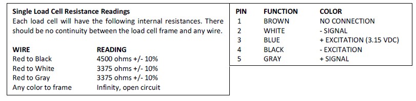
- Using an Ohmmeter, check the resistances of the four leads and compare them against the table. Also check each lead to each load cell frame looking for shorts. There should not be any continuity between the four load cell signal leads and any of the load cell frames.
- While the indicator is still in a safe area, install three charged batteries into the battery holder and secure the cover. Read and head the warnings in the next section before working with batteries.
- Once the battery is installed, move the indicator into the hazardous area and attach it to its mounting bracket. Tighten the thumbscrew.
- Connect the load cell/platform to the pigtail cable from the indicator. Single load cells purchased from Arlyn Scales will already have this connector attached.
- The scale is now ready to use. The system should be tested for proper operation prior to making the area hazardous.
Normal Operation
- Activate the scale by using the Main Power Switch on the rear of the unit to the “Battery” or “I” position. The scale will run a self-test procedure to check its load sensors and electronic circuitry. Upon proper completion, scale will settle on zero. Allow a five-minute warm-up time for stabilization and most accurate results.
- The scale can also be turned on from an external power supply through the barrier and turning off the battery switch using the Main Power Switch.
- Most pre-assembled scales come from the factory in a calibrated condition. There is no reason to do an initial calibration on these scales.
- If you are wiring the load cells yourself, the indicator may require setup and calibration. Please refer to the sections later in this manual for calibration instructions, or call Arlyn’s Service Department (800-645-4301 Ext 101) and we will help you through it. It is not a difficult or time-consuming process.
- Items to be weighed may be placed anywhere on the platform, but if heavy items are to be weighed, it is advisable to place them near the center. Many models are equipped with shock absorbers for protection. Still, care should be taken to avoid putting excessive stress on the load cell system, as when heavy weights are dropped on the platform. It is also important, especially in the case of large capacity platforms, that the platform not be impacted from the sides while there is a heavy load on the platform.
- It is normal for a small amount of zero drift to occur over short periods of time. For the most accurate readings, the scale may re-acquire a true zero by using the ZERO button just prior to weighing.
STARTUP CAUTION
Every time the scale is powered up, please wait at least 30 seconds before placing a weight on the scale or pressing any buttons. The scale has to initialize all its parameters and remember your previous settings and that takes a little bit of time.
PLATFORM LEVELING LEGS
Platforms will come with leveling legs that lifts the platform from the ground and provide the clearance for the internal load cell sensors to bend. At shipping, these leveling legs are screwed into the platform tightly (with no clearance) to protect the platform and the legs during shipping.
POWER MANAGEMENT
The MKE-5-IS Display Indicator can be powered from two different sources – internally housed Rechargeable Batteries or Optional External Power Supply (Intrinsically Safe External Supply or Power Supply through an approved barrier).
Battery Operation – Charging and Use
The MKE-5-IS Display Indicator is designed to use high capacity, three (3) AA 1.2V rechargeable batteries. The batteries can be changed by opening the screw-on battery cover on the left side of the indicator, and pulling out the discharged batteries. Newly charged batteries can then be inserted to power the indicator.
The scale firmware is designed to remember its “last zero” state. This means then since the scale will be turned off when changing batteries, after the scale is powered on again and connected back to the platform, it will not zero out the current weight on the platform. If this is not desired, then this setting can easily be changed.
 |
The rechargeable batteries used in this indicator have been approved by FM. The use of any other batteries violates FMs approval. Additional and replacement batteries must be purchased from Arlyn Scales. |
Battery Power Safety Considerations – IMPORTANT!
In order for this indicator to be safely operated in a hazardous area, battery care, operation and maintenance must be fully understood before you start the installation.
This battery holder was designed specifically for use in hazardous environments. It contains an internal current limiting circuit whose function it is to restrict the amount of power that the unit can supply, even if its outputs are shorted together. The battery holder is highly impact resistant, and designed to keep gasses, dust and other foreign materials out. When replacing batteries, you must ensure that there are no foreign materials inside the holder, and that the correct battery has been installed with the proper polarity.
Factory Mutual (FM) requires that the battery holder be designed in such a way as to eliminate any possibility of the holder coming apart and ejecting the battery if the unit is dropped or impacted sharply. In order to maintain this integrity, the cover must be securely fastened after installing the battery. Do not over tighten. Hand tightening is satisfactory. Failure to do so may cause the unit to eject the battery if the unit is dropped. The battery must never be exposed while it is located in a hazardous area.
AT NO TIME WHATSOEVER SHOULD THE BATTERY COVER BE OPENED WHILE THE SCALE IS LOCATED IN A HAZARDOUS AREA. DOING SO WOULD VIOLATE THE INTRINSICALLY SAFE DESIGN, POSSIBLY CAUSING AN EXPLOSION RESULTING IN SERIOUS INJURY OR DEATH.
Battery Charging
Batteries can be recharged using any standard charger designed to charge a 2000-2600 mAh NiMH AA cell. A charger is also available from Arlyn Scales. Most commercial chargers cannot charge a single battery so batteries are commonly charged in pairs.
The battery section explains this in more detail below.
|
Do not attempt to remove the battery cover while the unit is located in a hazardous area. Doing so will violate intrinsic safety, possibly causing an explosion or fire resulting in death or serious injury. |
To remove the battery, the indicator must first be moved to a safe area.
- Place the power switch in the OFF or “0” position.
- Disconnect the load cell cable from the upper right side of the indicator.
- Loosen the thumbscrew and slide the indicator housing off of the “L” shaped mounting bracket.
- Remove the indicator from the hazardous area.
- Once in the safe area, the battery may be removed and charged.
- Visually inspect the inside of the empty battery holder to ensure that there are no foreign materials inside. Also check to verify that there is no damage to any of the internal components.
- Insert a charged battery into the holder “PLUS” end first. Tighten the cover securely.
External Power Operation
The MKE-5-IS Display Indicator can be configured with the ability to be powered by an IS power supply or power supplies through certain approved barriers with matching Entity Parameters. See Doc #4013 – Installation and Wiring Diagram for further details. This is an optional method of powering the display indicator, available for purchase.
A typical external power supply configuration is a 4.3V DC supply from a safe (or unclassified area) passing through an ARL-BR-IS-PWR(-LC) safety barrier before entering the indicator’s external power cable.
External Power Safety Considerations
• Make sure the external power source matches the entity parameters and specifications of the MKE-5-IS Digital Indicator.
• If using a Safety Barrier, only approved barriers with matching parameters can be used for this operation.
AT NO TIME WHATSOEVER SHOULD THE MKE-5-IS DISPLAY INDICATOR BE POWERED DIRECTLY FROM AN UNCLASSIFIED OUTLET OR AN UNMATCHED APPROVED SOURCE OR BARRIER. DOING SO WOULD VIOLATE THE INTRINSICALLY SAFE DESIGN, POSSIBLY CAUSING AN EXPLOSION RESULTING IN SERIOUS INJURY OR DEATH.
Switching Between External Power and Battery Operation
The indicator can only be powered using one power source at a time. All MKE-5-IS Display indicator units are equipped with a 3-state SPDT (single pull double throw) rocker switch on the side of the indicator. The rocker switch is mapped as follows:
I -> Battery Operation
0 -> OFF
II -> External Power Operation
To utilize the external power supply (if available and connected), switch the indicator to “II”. The indicator will turn on once the supply begins.
The battery does not get charged automatically when the external power supply is used to power the indicator. It needs to be charged separately as indicated in various sections of this document.
Load Cell Wiring
|
Only Arlyn, FM approved load cells may be used. The list of approved load cells is as follows: 520-10000L-IS, 520-5000L-IS, 520-5000-IS, 520-2500-IS, 520-1250-IS 320-500-IS, 320-250-IS 620-300-IS, 620-100-IS, 620-50-IS, 620-25-IS, 620-10-IS |
The MKE-5-IS is equipped with a locking DIN connector on the upper right side of the housing for connecting load cells. In order for FM approval to be valid, the following must be adhered to:
- Only Arlyn, FM approved load cells may be used.
- Up to four of the cells from the above list may be connected to the scale.
- The type and length of connecting cables must conform to the control drawings.
- The maximum total cable length is not to exceed 133ft!
- Please consult control drawing 4013 for details on wiring, maximum lengths and obtaining extra, approved cable.
LOAD CELL CONNECTOR
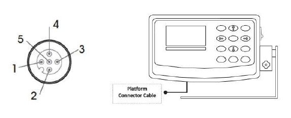
CONTROLS AND INDICATORS
MAIN DISPLAY SCREEN
The scale is equipped with 128×64 LCD Graphics Display with a wide viewing angle and variable contrast. For normal operations, you have a choice of viewing weight information from two main screens. For parts counting scales, two more screens are available. You can switch screens by pressing the MENU key and then press ENTER to accept the “Next Screen” menu choice. Doing this will step through the screens shown below in order. For non-counting scales screens 3 and 4 are skipped.
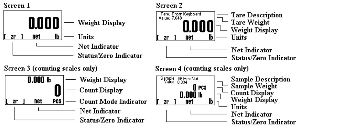
| WEIGHT DISPLAY | Shows the weight on the platform in the current units setting. |
| COUNT DISPLAY | Shows the active conversion units. |
| UNITS | Shows the active conversion units. |
| NET INDICATOR | Shows “Net” if the indicator is in net weighing mode. |
| STATUS/ZERO | Shows either “Zr” if the platform is at zero, a bar graph showing how close the scale is to maximum capacity or “OVLD!” if the platform is overloaded. |
| TARE DESCRIPTION | Shows the description of the active tare weight. If the tare was taken from the keyboard using the TARE key it will show “From Keyboard”. |
| TARE WEIGHT | Shows the weight value of the active tare. |
| SAMPLE DESCR | Shows the description of the active sample weight. If the sample was taken from the keyboard using the SAMPLE key it will show “From Keyboard”. |
| SAMPLE WEIGHT | Shows the weight value of the active sample. |
FRONT PANEL / KEYBOARD
The front panel has a twelve button, click touch key panel that allows easy menu navigation as well as full text and floating-point entry.
The main scale functions are shown in black, menu navigation and floating point numeric entry keys are blue and the secondary functions are yellow.
Main Function Keys
| ON/OFF | Press and hold to reboot the scale. On battery pack equipped scales, press and hold this key to power it down. |
| TARE | Tares any weight on the platform and switch the scale to the net mode. Hold the key down to clear the tare |
| NET/GROSS | Will toggle the indicator between the net and gross mode. The net mode will show the weight on the platform minus any tared weight. |
| UNITS | Pressing this key allows you to step through the various activated Units. |
| ZERO | Will zero the indicator. |
Menu Navigation Keys
| MENU/BACK | Using this key from the weight display will access the setup menu. In all other areas, it is used to back out from menus or to complete an operation. |
| ENTER | This key is used to select items and to complete operations in the various menus. |
| ARROWS | Use arrows to navigate and select menu items. |
Secondary Function Keys
| SAMPLE* | Used to acquire a quick parts-counting sample from the platform. Pressing and holding this key down will clear the active sample. *Parts Counting Scales only. |
| ACCUM* | Used to add the piece count to the accumulate register allowing the totaling of parts. Pressing and holding this key will clear the accumulate register. *Parts Counting Scales only. |
| ? KEY | Used in various areas to call up help screens. In some areas this key needs to be pressed and held. |
| SHIFT | Used by the text-editing screen to toggle caps on/off. |
| CLEAR | Used in some editing screens to clear input. In some areas this key needs to be pressed and held |
| NUMBER KEYS | Are used in various places to input floating point numbers. |
CALIBRATION
RECOMMENDATIONS
After familiarizing with various features and options available with the SAW Scale, please place the scale in the environment where the scale will be mostly used to get the scale acclimatized with its current environment. Take into account that the scale needs to warm up time of 10-15 minutes after boot-up.
OVERVIEW
- Before performing any calibration, the scale must undergo a Full Power Cycle. This means disconnect the scale from the power supply, wait a full minute, and then reconnect it back to the power supply.
- Once the scale is back on, allow 5-10 minutes of warm up time for initialization and stabilization. Do not operate the scale during this period.
- The scale is ready to be used. If accuracy is an issue, proceed to the next step.
- If the weight reading is off, perform Full Calibration as described below. Take note of any errors that may occur during this time. If the Calibration results in an error, refer to the Troubleshooting section for solutions. It is strongly to power cycle the scale once an error is encountered. This allows calibration to take place in a fresh state.
- If the Calibration fails repeatedly, or if problems with weight do not get resolved through Calibration, refer to Restore to Factory Defaults to restore working factory parameters that are built into the scale.
SAW SCALE FULL CALIBRATION
If the scale is not showing accurate values for a given weight on the platform, perform a Full-Scale calibration as described below.
- Scroll to PLATFORM SETUPS and press ENTER.
- MENU button (#5) —- setup menu screen will appear
- In the Platform Setups Menu, scroll to SPAN CALIBRATION and press ENTER.
- The next warning message warns you about the consequences of performing an incorrect calibration. Read the warning message, and then press ENTER
- Input the calibration weight on the space provided. The calibration weight must be at least 50% of full capacity. If you make a mistake, press ZERO until the mistake clears.
- Press ENTER to confirm input of calibration weight.
- Remove all weight from the platform. The current weight is shown at the top left side of the screen. Make sure that the reading is as stable as it can be. Then press ENTER.
- Wait for the next prompt to appear.
- When the prompt appears, place the known weight on the platform.
- Wait for the raw count on the top left side of the screen to stabilize (about 5 seconds). Press ENTER to confirm the placing of weight.
- Wait for a few seconds until the calibration procedure completes.
- Press MENU/BACK to go all the way back to the weight screen.
If at any time you received an error while performing this calibration, you must do a hard reboot of the scale (unplug the power adapter out and then plug it into the outlet again) to retry the calibration. See the Troubleshooting section for description of errors.
CAP ZERO (RESETTING THE CAPACITY SENSOR)
If the scale is turned on and the weight is not reading zero, or after placing the weight, the weight reading is not correct even after performing a Full calibration, then the Capacity Sensor in the scale needs to be reset.
- Press MENU button (#5) —- setup menu screen will appear
- Scroll to PLATFORM SETUPS and press ENTER.
- In the Platform Setups Menu, scroll to CAP ZERO and press ENTER.
- You will see the following message: “This will reset the capacity sensor. Remove all weight from the scale and press [ENTER] to continue”.
- Make sure there is no weight on the platform and press ENTER.
- Once CAP ZERO procedure is complete, go back to the main screen and then perform Full Calibration
SAW CORRECTION (ADVANCED OPERATION ONLY)
It is NOT recommended to perform this operation unless advised by a scale technician. The SAW Correction operation corrects the sensor’s slope in case it was adversely affected due to abrupt environmental change. To perform this operation correctly and effectively, the scale needs to be in a completely vibration-free and noise-free environment. Due to these stringent requirements, the operation may fail 50% of the time.
- Please follow the following steps to perform SAW Correction:
- Plug-in the scale, wait at least 10 min to let the scale warm-up.
- If the weight screen is not showing, press ON/OFF button on the indicator — the weight screen will appear.
- Press MENU button (#5) —- setup menu screen will appear
- Highlight PLATFORM SETUPS option (use the arrow buttons on the panel) and press ENTER button — the Platform Setups screen will appear.
- Highlight SAW CORRECTION line and press ENTER button.
- A prompt will appear asking you, “Would you like to perform a C1 parameter correction? Press [ENTER] to continue.” Press the ENTER button to proceed.
- A prompt will appear telling you to “Remove all weights from the scale and press [ENTER] to continue.”
- Make sure there are no weights on the platform, then press the ENTER button again on this screen —-the “Processing…” screen will appear. After sometime, the screen will turn back to Platform Setups.
- Press MENU button several times until reading screen will appear.
- Scale is ready to operate.
- If a timeout occurs during this procedure, please unplug the scale and repeat calibration from the start.
QUICK SAW CORRECTION (ADVANCED OPERATION ONLY)
You can perform a quick SAW Correction within 3 button presses without going through the entire process listed above. To do this, follow the proceeding steps.
- Press SHIFT (ON/OFF key) + ZERO. A prompt will appear asking you to remove all weights on the platform.
- Make sure there are no weights on the platform, then press the ENTER button again on this screen —-the “Processing” screen will appear. After that, just wait until the process completes. If a failure happens, remove the power cord from the outlet and then plug it in again. Then try the calibration process again.
That’s it. You don’t need to do anything else. Place a known weight on the platform to check if everything is reading okay.
If at any time you received an error while performing this calibration, you must do a hard reboot of the scale (unplug the power adapter out and then plug it into the outlet again) to retry the calibration.
SYSTEM OPERATION
Basic Menu Operation
The scale operating system uses a menu driven interface that is both intuitive and easy to use. To access the setup menu press the MENU/BACK key.
There are two basic menu types. The first is a simple list of items. To select an item in the list, use the UP and DOWN ARROW keys to line up on the desired item and then press ENTER.
The second type of menu is a horizontal list displayed along the bottom of the screen. These menu items indicate operations to be performed. To select one, use the RIGHT and LEFT ARROW keys to select the desired item and then press ENTER. Horizontal menus may show a single or double headed arrow on the right side to indicate that there are more selections to the left and/or right that are not displayed.
Horizontal menus and lists are often used together to perform an operation on a specific item. For example, to delete a tare entry, use the UP and DOWN ARROWS to select the desired tare from the list, then use the LEFT and RIGHT ARROWS to select the menu item “DEL” in the horizontal menu. Pressing ENTER will perform the operation.
Selecting menu items will often lead to other menus, sometime drilling down several levels deep. Use the MENU/BACK key to back your way out. Continuing back will eventually bring you back to the top, which is the main weight display screen. Consult the menu tree in the back of the manual for help in navigating menus.
Tare Functions
The tare function allows you to temporarily remove from the display any weight that may be on the platform. Tare weights are often used in filling processes. For example, the user will place an empty box on the platform. The scale will indicate the weight of the box. The user then presses the TARE key. The scale will now indicate a weight of zero, and will switch to the NET mode. The box can now be filled. The scale will read out only the weight of the material. Switching to the GROSS mode will show the weight of the material plus the weight of the box. To clear any active tare, press and hold the TARE key.
Tare Settings and Tare Definitions
Tares can also be taken, named, activated and stored permanently through the setup menu. Go to menu SETUP MENU/TARES. A list of
options is displayed on the screen, Tare Definitions and Tare Settings.
Tare Definitions
In this screen, a list of all tare definitions will be shown. To add a new tare, line up on NEW in the lower menu and then press ENTER. A new tare will be added to the list with the default description of Tare #XXX. The number XXX is assigned by the system by counting up the number of tares and then adding one. It is possible that after adding and deleting a few tares that two tares will have the same description. This is acceptable, albeit confusing, and the description can be changed later. This new default tare will have a weight value of 0.00 lb when first created.
Editing Tares
You can edit any tare by using the arrow keys to line up on it and the “EDIT” function in the lower menu and then press ENTER. The next screen will show the tare with its description and weight value in pounds. The lower menu allows you to change the description(“DESCR”), enter the value directly (“VALUE”) or acquire it automatically from the platform (“ACQUI”).
Deleting Tares
To delete a tare from the list simply line up on it and the “DEL” function in the lower menu. Press ENTER to delete it. Once a tare has been deleted it is removed permanently from memory.
Activating Tares
To activate a tare from the list, line up on it and the “ACTV” function in the lower menu, then press ENTER. The tare will be made active, the scale switched to NET mode and you will immediately be placed back in the weighing screen you were in when you accessed the setup menu.
Tare Settings
In this screen, the way the tares behave can be changed. This also depends on what options you have installed in your system. The selection settings can be changed using the horizontal menu at the bottom of the screen. The following selections apply.
Persistent Tare (For all scales)
Selecting this option to “Yes” will allow the scale to maintain the tare activation even when the power is recycled. This will apply to both, stored tares and quick tares (tares from the keyboard). So, if the user activates a Tare from the Tare Definition Screen, and recycles power, the scale will remember the last tare activated. Please note that when the scale is turned on the next time while a tare has been activated, the scale will not show “0” with an empty platform. There will be negative number that will likely show up on the screen corresponding to your tared value. Selecting this option to “No” will remove the persistent tare feature. Tares will not be remembered after power is recycled.
The System Menu
The system menu contains many useful features for checking and configuring your scale. To access, press the MENU button, then select SETUP MENU->SYSTEM.
Any feature that is not described here should not be touched. Any attempt to do so may severely affect your scale. Each feature is outlined below.
Backup
Use this function to create a backup of the current scale configuration internally. Use this function and follow the prompts on screen to
perform a backup of your scale.
Restore
Use this function to restore a backup of a previous scale configuration. This is helpful if you already created a backup of your previous working configuration. Use this function and follow the prompts on screen to restore of your scale to a previous backed up configuration.
Restore to Factory Defaults
If the scale is not performing properly, and all other troubleshooting methods have failed, then the last resort is to restore the scale back to its factory calibrated settings. Use this function and follow the prompts on the scale to complete it.
To restore the scale back to Factory Defaults, perform the following steps:
- Completely unplug the scale. Wait for a few minutes, then re-plug power to the scale.
- Press the MENU button and go to SYSTEM. Press ENTER.
- In the System Menu, scroll to SAW Scale Setup and then press ENTER.
- Scroll down and select RESTORE TO FACTORY DEFAULTS. Press ENTER.
- If there are any warnings that popup, just press ENTER to confirm.
- If the Restore was successful, the scale will automatically reboot.
- Wait for the scale to settle.
- Place a test weight to see if the scale is reading appropriately.
Startup Parameters
The following startup parameters can be set here:
- The startup screen and conversion units can be set here.
- Zero lock can be enabled/disabled. Zero lock disables the front panel ZERO key. When this function is enabled the user must press the ZERO and the PRINT key simultaneously to zero the scale.
- Show SAW ST Screen at Startup. This allows you to see the SAW Platform Status screen at startup. Disabled by default.
Scale Description / Scale ID Number
Each scale can be assigned a unique description and ID number. This is useful for printing labels and other processes.
Udef Conversion Multiplier
Allows you to enter the multiplier (from pounds) for the user-defined conversion.
Display Contrast
Allows you to adjust the contrast of the display for optimum viewing.
Display Refresh Interval (or Display Update Speed)
The Display Refresh Interval can be adjusted from .1 to six seconds.
Auto Shut-Off
Auto Shut-Off allows you to set your scale to automatically shut off when a preset time limit has been reached and there has been no activity on the scale. This feature is mainly used on battery pack equipped scales to prevent the battery from inadvertently being deep discharged. Auto Shut-Off can also work on non-battery equipped scales but its operation is slightly different. In a battery equipped scale the unit will completely shut down and the display will blank. The scale can later be turned on again using the normal means. On non-battery equipped scales, the display will blank but the scale will remain in the same condition as when it shut down. Zero, active tare and active parts counting sample as well as the current screen will all be retained. Pressing any key will return the scale to its normal operating mode.
An inactive scale can be defined as no keys being pressed, and there has been no activity on the platform. It should be noted that anything that causes a small increase or decrease in the platform reading will be considered an active platform. Avoid vibrating surfaces, digital filtering constants of non-factory default values, or anything else that causes the platform reading to drift if this feature is used.
To configure Auto Shut-Off, go to the menu SETUP MENU/SYSTEM/AUTO SHUT-OFF. There are two settable options available.
Activate – ACT Activates/deactivates the auto shutoff feature.
Time Interval – TIME Is the time, in minutes, that the unit will shutoff due to inactivity. Any time from 1 to 25 minutes can be used.
Decimal Truncation
This function allows you to truncate the least significant decimal place from the displayed weight. This does not affect the readability and the accuracy of the scale. It also does not affect the weight outputs to the various communication options.
CONFIGURATION AND CALIBRATION
PLATFORM SETUP
To access the Platform Setup Menu, press the MENU button to bring up the Setup Menu. Select PLATFORM SETUPS option and press ENTER.
The sections below describe what each selection does in this menu. Any option that is not described here should not be touched. Any attempt to do so may severely affect your scale.
Important Selections
The two most important selections are:
- Span Calibration
- SAW Correction
Span Calibration
Span calibration adjusts the platform’s sensitivity so that the display reads correctly. A calibrated weight is required to perform this and the procedure is outlined above in the SAW Scale Full Calibration section.
SAW Correction
This procedure corrects parametric deviances that naturally occurs over time with the SAW load cell. Whenever the scale starts to show some odd behavior (such as weights not reading accurately, or slight jumping), this should be the first procedure to try to mitigate these issues.
Other Items
Other selections on this menu are:
- Edit Description
- SAW Diagnostics
- *Resolution-Overload*
- CAP Zero
- Zero Tracking
- Stability Control
- Software Filter
- Zero/Motion Detect
- Auto Zero
- *Platform Auto Setup*
- Load Cell ID#
*These items are for Advanced Use only. Accessing and changing them in any way without proper supervision would adversely affect your scale.
Parametric Settings
Edit Description
Allows you to edit fourteen-character description can be assigned to the platform. The default description is “P1”. This should not be changed for any reason unless you want to the description as part of your Print Frame. However, changing the description will not affect the metrological properties of your scale.
Resolution-Overload
This setting should not be changed unless instructed by a Service Technician.
The scale has the capability of displaying its reading in any of eight standard conversion units. Only four are enabled by default and the user can enable the rest. The conversion units that are automatically enabled are pounds, kilograms, grams and ounces. The remaining conversions are troy ounces, pennyweights, grains and a user defined conversion.
Each conversion unit’s resolution can be set individually. To do this, select RESOLUTION-OVERLOAD from the platform menu. A list of conversions is displayed and each active conversion will have a check mark to its right.
Select the conversion you wish to modify and press ENTER. Use ACTV to activate/deactivate it, DPNT to change its decimal point location and CNT to change what the least significant displayed digit will count by. In the pounds configuration (the scale’s native conversion unit) you can use OVRL to set the overload limit in pounds.
When setting resolution (DPNT and CNT) care must be taken not to exceed 5000 total displayed counts or a drifting reading may result. The maximum resolution is setup by default by auto setup but can be calculated easily by taking the scale’s maximum capacity and dividing it by 100,000. For example, a 50-pound scale’s resolution should be .01 pounds (50 / 100,000 = 0.0005).
CAP Zero
One of the sensors equipped in the scale is called a Capacitor Sensor. Sometimes, this sensor loses its Zero Reference value due to a sudden change in environmental conditions or unexpected user interaction with the scale. This selection performs what’s termed as “Capacitor Zero” operation of the scale. It basically restores the Zero Reference point of the Capacitor Sensor. This operation is useful when the scale is not behaving properly and not weighing properly. When experiencing problems, if SAW Correction does not fix the issue, then CAP Zero operation should be performed next.
Auto Zero
Auto Zero determines how the platform will zero on power up. The following selections apply.
Auto Zero – With this option selected, the scale will automatically zero out any weight on the platform. This is a good option for environments that are not prone to power failures. Also, it is a great option if you always want to start the scale at zero regardless of what the state of the platform (loaded or unloaded).
Last Zero – At initialization, the scale will zero out the platform to the last preserved zero state when the ZERO button was pressed. This means that the scale remembers the last time the ZERO button was pressed. This results in the scale remembering the value of the weight currently on its platform when the scale is shut off. In addition to that, suppose the weight was changed after the scale was shut off, the next time the scale is turned out, it will show the new weight. This is an excellent option for environments prone to power failures. It is also an excellent option if you need to constantly monitor the weight on the platform without interruptions.
None – The scale will initialize the platform based on its previous state. It is not a recommended to leave the scale in this option. The scale may start up with an unknown state.
Filtering and Accuracy
Zero Tracking
A scale sitting for long periods of time without weight on the platform is prone to drift from zero due to temperature changes and a number of other factors. Generally, this is not a problem and you can press the ZERO button to return the reading to zero before weighing. Zero tracking, when enabled, will detect small reading changes over time and correct the platform back to zero.
There are four settable options on the setup screen. To modify them, use the left and right arrow keys to line up on the appropriate entry in the horizontal menu located at the bottom of the screen, and then press ENTER. These menu items are as follows:
Active – ACTV: Activates or deactivates Zero Tracking.
Window – WIND: This is the window range above or below the current ZERO point that needs to be continuously compensated (up to 20% of full capacity) to correct zero shift. For example, over two days, you notice that the scale has shifted in weight by 0.2lbs, even though there is no weight on the platform (and was originally reading perfect 0) or a weight that was constant over two days is now reading 0.2lbs over. This is known as “Zero Shift” and can be corrected using Zero
Tracking. After studying the scale’s behavior on this aspect, we can plug this 0.2lb range in this Window field. Now you will notice that your scale will zero out any deviations that falls within ±0.2lbs.
Noise Count – NCNT: This is the noise count of filtering mechanism. This sets the number of weight values that need to be discarded before considering that the new weight value is a new value and not part of the current weight value tracking process. The higher this number, the less accurate the weight value, the faster your performance.
Software Filter
The raw internal reading from the load sensor contains electronic noise and other factors that can cause the reading to be drifty and non-repeatable. All electronic scales incorporate some sort of filtering to compensate for this. Another use for filtering is to help stabilize a scale when it is used on a surface that is vibrating, in windy conditions, when subjected to RF interference or when used on a noisy power line. Your scale has two stages of filtering. The first is an electronic filter that is permanently enabled and the second is the software filter which is fully configurable.
In general, a low degree of filtering will cause the scale to be quick to react but prone to noise and vibrations. Heavy filtering will eliminate the noise and vibrations but the platform will react slowly to changes in weight. We have by default set up the optimum filtering parameters for general use. These should only be changed in extreme circumstances.
There are four settable options on the setup screen. To modify them, use the left and right arrow keys to line up on the appropriate entry in the horizontal menu located at the bottom of the screen, and then press ENTER. These menu items are as follows:
Active – ACTV: Activates or deactivates Software Filter.
Buffer – BUFFER: These are the number of averaging slots in the software filter. The higher this number, the slower the filtering process, the more accurate the weight reading.
Window – WIND: Set’s the weight value window at which you want the filtering to take place. The standard value for this field could be the scale’s resolution. So, if your scale is at a resolution of 0.02 lb, then set that value to this window. By default, the value has been set in factory.
If you set a lower value than the resolution of the scale, then the scale will be stricter in its filtering and almost all values from the platform will be hitting the noise count giving you a much slower performance.
Set a higher value and the scale will be more lenient in its filtering allowing more noisy values to pass through for processing giving you a better performance but higher inaccuracy in readability. The best way to approach this window is determining the range of fluctuation with the default setting. For example, by observing the scale, you notice that your scale is varying by 1lb. If that is the case, then set the value here to 1lb. You will then get stable readings within this range.
Noise Count – NCNT: This is the noise count of filtering mechanism. This sets the number of weight values that need to be discarded before considering that the new weight value is a new value and not part of the current weight value averaging process. The higher this number, the less accurate the weight value, the faster your performance.
Stability Control
If the scale display values are not stable due to a noisy or unstable environment and you do not want to estimate the actual value of the weight on the platform, the scale can estimate it for you.
Stability Control is not by any means a filtering mechanism. This feature should only be used if you know that the scale will always be unstable or in constant noise. What this feature does is lock in an appropriate weight based on the stability count and a stability window you have specified in this screen. The weight locked, may not be the most accurate weight of the object placed on the platform, but it is a best guess as computed by the Stability Control in this scale. Once the stability lock has been placed, the lock will not be removed until the platform experiences a weight change greater than the stability window. There are four settable options on the setup screen.
Active – ACTV: Activates or deactivates Stability Control.
Source – SRC: This sets the primary source of readings that the Stability Control mechanism will use to estimate the best lock-in weight. There are two selections here:
- A/D Reading – This selection makes the Stability Control mechanism take readings unfiltered and straight from the load cell. This is the fastest and the least complex selection and therefore the default.
- Filtered – This selection is an advanced selection. With this selection, Stability control uses filtered weights based on parameters set by the Software filter. Selecting this option automatically activates software filter. Make sure the parameters in Software filter are properly set or the scale will behave erratically. Use this selection only if you know what you are doing.
Window – WIND: The Window field operates similarly as explained in the Software Filter section.
S.C. Count – CNT: This number indicates the number of stable readings within the window set above to qualify a lock in. Suppose this number is set to 3, then the Stability Control mechanism will try to read 3 readings consecutively that are within the window above. If they fall within that window, then the weight will lock in, else, it will reset and start over until it gets 3 stable readings.
Noise Count – NCNT: This is the noise count of filtering mechanism. This sets the number of weight values that need to be discarded before considering that the new weight value is a new value and not part of the current weight value averaging process. The higher this number, the less accurate the weight value, the faster your performance.
After Stability Control is activated, an “S” appears at the bottom left of the screen during normal weight readings. While the scale does not have a stable reading, the S will appear crossed out. As soon as a weight has been found, it will lock this weight and the S will be uncrossed. Once the lock has been obtained, the reading will not budge until a weight change greater than the window set has occurred.
Zero / Motion Detect
This scale can detect if there is motion on the platform. There are four settable options on the setup screen. The first three are for the motion detect setup. The fourth option controls the zero indicator on the main display. To modify them, use the left and right arrow keys to line up on the appropriate entry in the horizontal menu located at the bottom of the screen, and then press ENTER.
Active – ACTV: Activates or deactivates motion detection.
Motion Window – MOTN: The Motion field determines the range of weight at which you want to define “motion”. So, if the scale has been set on a moving truck, and you have determined that the scale always is within a certain weight range when the truck is moving normally at normal speeds, you would want to set the Motion window at that range. For example, say you have put a weight on the scale that would read 20lbs on a stable surface. But on the truck, it reads 18-23lbs. This means that your motion window is 5lbs. So now you know that you want to detect motion if and only if it is greater than 5lbs, so you can set the Motion window to 5lbs.
Time Interval – TIME: This works along with Motion Window to detect a stable reading. The reading must be stable within the motion window for this length of time (in seconds) in order to be considered a stable reading. As long as the weight remains within specified motion window within this time, the scale would confirm that there is no motion detected. If the weight jumps out of the motion window, then the scale would register as “Motion Detected” and reset the time interval.
Zero Window – ZERO: This controls how close the scale needs to be to the true zero point before lighting the zero indicator (ZR) on the bottom of the main display. For example, if you set the window to 1lb, then any weight from 0lb to 1lb will register as ZR (meaning ZERO condition).
After ZERO/MOTION DETECT is activated, the scale needs to be rebooted for this option to take effect. After reboot, a tiny ‘?’ indicator appears at the bottom of the screen. If the platform is moving, the ‘?’ indicator will show as it is seen here. If the platform is within the bounds of ‘No Motion’ as set here, then the ‘?’ indicator will be crossed out.
Advanced Setup and Diagnostics
SAW Status
This screen checks all the sensors in the SAW platform to make sure they are operating within a certain range. If the parameter readings are all within expected range, the sensor status will show “OK”. Otherwise, it will show as “Fail”.
SAW Diagnostics
Shows the digital raw parameters of all the sensors equipped within the scale. This screen is primarily used for service and troubleshooting.
Platform Auto Setup
This setting should not be accessed unless instructed by a Service Technician.
Auto Setup will erase all of the parameters for the selected platform and return it to the default state. It also erases the platform’s span and cornering calibration. Auto setup is useful when the scale is first manufactured or when the user inadvertently changes a calibration parameter that adversely affects the scale and then forgets the calibration parameter or its original value. Upon activation, you will be presented with a selection of platform capacities and resolutions. Pick the appropriate entry and then press ENTER. Auto setup will be performed. A span calibration is now necessary.
TROUBLESHOOTING
Your scale has been precisely calibrated at the factory before shipping. It has the capability to adjust its own calibration to a certain degree to compensate for aging electronics, and temperature changes. This being the case, it is possible that you will never have to calibrate the scale. Doing so may leave you with a worse calibration than you started with. Does your scale really need to be calibrated? If so what steps are needed? Follow the steps outlined below to help make this determination.
Scale reads zero and will not move
- Make sure that any and all shipping screws are removed from the platform.
- On platform scales, check that all four level legs are contacting solidly against the floor.
- If level legs are screwed in all the way then the stud from the level leg may be contacting the underside of the platform not allowing the load sensor to flex.
- Check to see if the SAW platform is securely connected to the Digital Indicator.
- Check SAW Diagnostics and see if all the numbers shown on this screen are constantly moving. If any of the numbers is showing 0.000, please call customer service for further assistance.
- Perform a Full Power cycle (disconnect the scale from the outlet) and then perform a SAW Cap Zero.
- Perform “Restore to Factory Defaults” to fix the issue.
Scale reading is fluctuating wildly
- Scale must be on a non-vibrating surface. Breezes may affect scales of all capacities. Breeze/Wind is much worse than vibrations because wind is additive. It is difficult to filter out the wind added noise. The scale must be put in an environment where wind is not a factor.
- Scale must be installed on a clean power line. Electric motors, computers or any other devices can cause power line interference.
- RF interference can cause scale readings to fluctuate. Are there any transmitters nearby like cell phones or walkie-talkies?
- If the scale is a remote platform type, check to see if the cable from the platform to the indicator in plugged in properly. If so then remove the plug temporarily to check for bent or missing pins.
- Check for nicks or cuts on the platform cable.
- Perform a Full Power cycle (disconnect the scale from the outlet).
- Perform Cap Zero.
- Perform Full Calibration
- Perform “Restore to Factory Defaults” to fix the issue.
Scale reading is different on different areas on the platform?
- On platform scales, check that all four level legs are solid against the floor. If a level leg is screwed in all the way then the stud from the level leg may be contacting the underside of the platform not allowing the load sensor to flex.
- Check for any mechanical interference. Is there anything rubbing against the platform?
- Perform “Restore to Factory Defaults” to fix the issue.
Scale corners properly but does not indicate the correct weight.
- On platform scales check that all four level legs are solid against the floor.
- Check for any mechanical interference. Is there anything rubbing against the platform?
- Perform a Full Power cycle (disconnect the scale from the outlet) and then perform a SAW Correction
- Perform Cap Zero Reset Operation.
- Perform Full Calibration.
- Perform “Restore to Factory Defaults” to fix the issue.
MENU TREE
INTRODUCTION TO OPTIONS
This section will cover the operation and setup of all of the options available for your scale. It is important to note that some described menu items will be missing if that option was not installed in your specific scale. All of the options listed may be installed in any scale and may run concurrently. Any of the options may be installed later at the factory if it wasn’t installed at time of purchase. Call our service department for details.
RS422 COMMUNICATION
The RS422 option is a fully capable, bi-directional communications port. The port can be configured to operate at a variety of baud rates and the output data frames are definable by the user. The printing of a frame can be initiated by pressing the print button, by an external command or continuously when the print stream mode is activated.
The communications port also contains an extensive external command interface allowing the ability to perform remote key presses.
CONFIGURING THE PORT
Baud rate and other parameters can be configured through the Port Configuration screen that can be accessed under menu SETUP MENU/OPTION SETUPS/RS232/PORT CONFIG. The options are shown below.
| BAUD RATE | Settable to 110, 150, 300, 600, 1200, 2400, 4800, 9600, 19200, 31250 or 38400 bits per second. |
| DATA BITS | Seven or Eight |
| STOP BITS | One or Two |
| PARITY | Even, odd or none |
| ECHO | On or off. When echo is enabled the scale will echo each character the scale receives back to the user. |
PERFORM TEST PRINT
As an aid to port configuration we have included a “perform test print” function to the RS232 menu. Executing this will cause your current Print Frame to print. To access this function, go to the menu SETUP MENU ? OPTION SETUPS ? RS232 ? PERFORM TEST PRINT.
This selection is also available as part of the USB Communications option.
LOOP BACK TEST
You may also test the operation of the RS232 port by performing a loop back test. On the output connector, TX and RX (transmitted and received data) need to be shorted together. When you perform the test, the scale sends data and reads it back through its own port, where it is compared and the results are show.
PRINT STREAM MODE
Print stream mode will continuously print the currently active print frame at fixed time intervals. Stream mode can be configured using menu SETUP MENU/OPTION SETUPS/RS232/PRINT STREAM. The lower menu selection ENB will enable or disable print stream mode, and TIME will be the number of seconds between the beginning of each print frame. Time settings of .5 to 1638 seconds (27.3 minutes) can be entered. Avoid using time values of less than .5 seconds as it may slow down or lock up the scale.
When stream mode is enabled, use the print button or the external *P command to start or stop the printing process.
This selection is also available with USB Communications Option.
PRINTING AT STABILITY USING MOTION DETECTION AND STABILITY CONTROL
All Arlyn digital indicators have the capability of detecting motion and/or stabilizing the weight and using it to control printed outputs. This can be useful in many applications. For example, if you wanted to print labels for several items, you could simply place each item on the platform, and when the scale gets a stable reading it will print the label automatically. The Motion Detect, Stability and printing at stability are fully configurable through their respective setup screens.
The Motion Detect indicator looks like an ‘M’ and it is located just to the right of the Zero Indicator / Bar Graph located on the bottom of the display. It is crossed out if there is no motion, and it is uncrossed if there is motion.
The Stability Control indicator looks like a circle and it is also located just to the right of the Zero indicator/Bar Graph located on the bottom of the display. The circle is unfilled when the weight is not stable and filled when the weight is stable.
Print at Stability configuration allows the user to choose what control they want to use to print. The user can choose Motion Detect only, Stability control only, or both Motion Detect and Stability control. Take a look at the Instructions Manual to see how the Motion Detect and Stability Control can be set.
Sending a PRINT command or pressing the PRINT button on the front panel will send a PRINT request to the scale, and the scale will only print if the motion and stability conditions are met.
This selection is also available with USB Communications Option.
The Print-At-Stability Setup Screen
Follow the menu tree down this path to locate this setup screen: SETUP MENU / OPTION SETUPS / RS232 / PRINT AT STABILITY.
There are five settings that control this function:
Activate – ACTV: This will activate or deactivate this function. Select ACTV from the horizontal menu on the bottom of the screen, and then press ENTER to change this setting.
Percentage of Capacity – PCT: This is the percent of full scale capacity, which, if the scale reading falls below, will not automatically print. For example, a 100lb full capacity scale set to 1% will not automatically print when there is less than 1lb on the platform. In most applications, there is no purpose to generating a print after removing weight from the platform. This percent can be set to two decimal places.
Stability Timeout – TIMEOUT: This is the time set by the user to timeout retrieval of the value after a certain period of time. By default, this value is 0, which means that the scale is never going to timeout to print a weight values. It will continue to look for a stable point to retrieve a weight value for printing. If the number is set other than 0, then this is the period that the scale will try to print a weight value, and if it fails, it will print “TIMEOUT” in ASCII on the terminal.
Negativity – NEG: By setting this to “YES”, the automated print will work on both sides of zero. When set to “NO” it will only work with positive weights. The user must take into consideration here that if this parameter is set to “NO”, then when the scale is reading zero, the output may be erratic even though the scale is stable. This is because the value 0 in the scale is not a true stable zero. The zero here may be a long decimal that goes beyond the resolution. In this case, the value maybe negative and therefore, impeding the printing process. It is recommended to set this to “YES” if the zero value is important.
Zero Notify – ZERO NTFY: If this option is set to “YES”, then each time the scale is zeroed or a zero command is sent through one of the communication ports, the indicator will wait for the scale to stabilize and detect if there is no motion. Once these conditions are detected, the word “ZERO” appears on the output terminal in ASCII.
Control Source – CONTROL: This option can be switched between Motion, Stability, Motion and Stability based on your preferences. This determines how you want the Print at Stability to operate, whether based on Motion Detect, Stability Control or both. It is important that when you choose these options, these features need to be activated within the system to operate properly.
Print Stream Mode with Print-At-Stability
Print Stream and Print at Stability can work together. If you want the scale to print weights constantly, then activate both of these features together and they will work in tandem with each other.
PRINT FRAME
The print frame is a list of up to 20 functions for the scale to perform each time a print request is received. The list is executed in the same order as shown is shown. A function can either be an item to be printed or a command for the scale.
With the MKE-5 indicator has the ability to store only one frame. For the capability of defining multiple frames, please look at our Arlyn UpScale Touchscreen Display.
This selection is also available with USB Communications Option.
Defining and Editing the Print Frame
Go to the menu SETUP MENU/OPTION SETUPS/RS232/PRINT FRAME.
Default Print Frame
By default, the Print Frame has two functions stored; Weight and Unit with Carriage-Return (CR) and Line-Feed (LF) at the end of the Frame. This allows the scale to print out the weight and unit to the RS232 output.
This is what a 25.5lb weight would look like on a 620L scale equipped with RS232 (or USB/Ethernet/RS485) printed on Serial Port Terminal:
25.50 lb
Defining a Custom Print Frame
To re-define the frame, line up on NEW on the lower menu and then press ENTER to add a function. The function NULL will be added to the list. We want to change this to the WEIGHT function. Press the right arrow key to line up on FNC+ on the lower menu. Press ENTER twice to select the WEIGHT function. To add a CR to this function, use the right arrow key to line up on CR on the lower menu and then press ENTER.
You will then see a check mark under the column “C”. To turn on the LF, press the right arrow once more to line up on LF and then press ENTER. This completes the definition.
The lower menu items on the frame editing screens are outlined below.
| Selection | Description |
| NEW | Adds a new default function (NULL) to the function list. |
| INS | Inserts a new function (NULL) before the currently selected function line. |
| DEL | Deletes the currently selected function line. |
| FNC+/- | Changes the function of the current line. Available functions and their explanations are outlined below. |
| SRC | On many of the functions you need to specify the source of the data. For example, the WEIGHT function must know what platform (on multiple platform scales) the reading should come from. SRC will step through all available platforms. |
| CR | Includes a carriage return at the end of the current function |
| LF | Includes a line feed at the end of the current function. |
| SP | Allows you to print space(s) at the end of the current function. When activated a “?” will show up in the function list on the current line and allow you to enter a number. The number of spaces must be between 0 and 15. |
| TEST | Quickly test the print frame without having to return to the scale’s normal operating mode. (Future Expansion) |
Print Frame Functions
You can add up to 20 functions to Print Frame. The functions are executed in the order they are defined in the list. You can add a CR (carriage return), LF (line feed) or trailing spaces to most functions. This is useful when designing labels.
Function List
| Function | Action |
| NULL | Does nothing, but allows CR, LF and spaces to be printed. |
| WEIGHT | Prints a six-digit weight value. It will be net or gross depending on mode. Use SRC to select the platform. |
| NETWGT | Prints a six-digit weight reading corrected for tare. Use SRC to select the platform. |
| GRSWGT | Prints a six-digit weight value ignoring any active tare weight. Use SRC to select the platform. |
| NGTEXT | Prints “NET” or “GROSS” depending on mode. This is meant to be used with the weight function. Use SRC to select the platform |
| PLATTOT | Prints a gross total reading of all active platforms. |
| COUNT | Prints the current piece count. Use SRC to select the platform. |
| ACCUM | Prints the value in the parts counting accumulate register. Use SRC to select the platform. |
| CNTACC | Prints a total of the current piece count plus the part count in the accumulate register. Use SRC to select the platform. |
| TIME12 | Prints the current time in 12-hour format. (when the time and date option is installed) |
| TIME24 | Prints the current time in 24-hour format. (when the time and date option is installed) |
| DATE | Prints the current date in the format as selected in the Date Format in Time and Date Option Configuration. (when the time and date option is installed). |
| SCADES | Prints the 14-character scale description as entered in the system menu. |
| SCAID# | Prints the scale ID number as entered in the system menu. |
| WEIGH# | Prints the auto-incrementing weigh number who’s starting value was entered in the system menu. This number will increment each time a frame is printed. |
| TEXDEF | Prints a 14-character text string that was entered as a text definition. Use SRC to select the text definition. |
| UNITXT | Prints a 3-character indication of the currently selected unit conversion. (lb, kg, oz, etc). |
| TARDES | Prints the 14-character description of the current active tare weight. |
| SMPDES | Prints the 14-character description of the current active sample weight (parts counting). |
| ASCII | Will send a single ASCII character to the port. Among other things this is useful to send ESC sequences to the printer to change fonts etc. Use SRC to enter the ASCII code. |
| CHFONT | Change Font. Works only with EPSON compatible printers. Use SRC to select the font. See explanation below. |
| CHPNT | Change Point size. Use SRC to toggle through the choices 16,20,24,30,36,40,42,48,52,56,60,64 |
Print Frame Design Examples
Simple Weight Print
The first example is a simple print frame that will print the weight followed by a carriage return and a line feed.

EXTERNAL COMMAND INTERFACE
The external command interface allows the user to control the scale and manipulate memory data through the RS232 interface. There are three basic command types, these are:
The * Command (Keyboard Emulation) – This allows you to simulate key presses remotely.
It should be noted that the command list described below is the proposed list of commands. As our scale continues to develop, commands are added as each firmware revision comes out. The revision in which the command was added is shown just to the right of the command in parenthesis. If (X) is indicated it means that the command has not been implemented yet and is slated for future release. To check the revision number of your scale, watch the Arlyn Logo splash-screen when you first turn on your scale. Firmware upgrades can be purchased and installed in your indicator. . Some commands can be implemented based on customer request. If it is imperative for the customer to have a certain command type, contact our service department for more information and to get quote for the functionality to be implemented.
Print Request Response Time
When the scale receives a print request (*P) there is a small time-delay while the scale computes and formats its output frame. For any frame function that outputs weight or parts count the response time is typically 100 milliseconds (1/10th second). For almost all other frame functions the response is almost immediate.
External Command Limitations
It is important that when sending repeated print requests (*P) to the scale that you wait for the scale to completely transmit its print frame, and then wait a small amount of time before sending the next request. If the scale receives a print request while it is still transmitting, the scale could actually lock up requiring a power off reset. Also, it is advisable to wait a small amount of time after the output frame is complete to give the scale a chance to do its own “housekeeping chores”. To immediately send another print request directly after a transmission could bog down the scale’s displayed update rate and keyboard response.
The [*] Command: Used for Keyboard Emulation
A number of external commands can be sent to the scale to simulate keyboard presses. These commands are listed below. Each command must be prefixed with a * character and no CR is required.
| Command | Keypress |
| *P or *1 | Print Key – (1) |
| *C or *3 | Units Key – (3) |
| *Z or *0 | Zero Key – (0) |
| *N or *9 | Net/Gross Key – (9) |
| *T or *7 | Tare Key – (7) |
| *U or *8 | Up Arrow Key – (8) |
| *D or *2 | Down Arrow Key – (2) |
| *L or *4 | Left Arrow Key – (4) |
| *R or *6 | Right Arrow Key – (6) |
| *. | Decimal Point – (On/Off) |
| *O | On/Off Key will reboot the scale. Power down mode in Battery. |
| *M or *5 | Menu/Back Key – (5) |
| *E | Enter Key – (Enter) |
Care must be taken when sending key commands via RS232 as some keys will perform different functions depending on the scale’s operating mode.
TEST USING TERMINAL
You can also test the scale communication using a Serial Terminal. To do this, first you will need to download a suitable terminal (if you don’t have one). We recommend RealTerm (https://sourceforge.net/projects/realterm/files/)
Direct Link to File: https://sourceforge.net/projects/realterm/files/latest/download?source=files
In RealTerm (or your favorite terminal), setup the connection using the COM port of your Serial Communication.
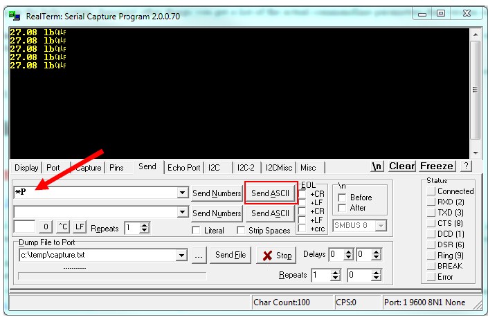
Make sure the Port designation on the bottom right of the screen shows the correct connection parameters. Then press the PRINT button on the scale to start sending data on to the terminal.
Alternatively, you can also send Print Command to the scale to retrieve weight. Use the Send Tab to do this:
RS485 COMMUNICATION
The RS485 communication framework is similar to the RS422 Communication Framework. The RS485 Communication option is a fully capable, bi-directional communications port. The output data frames can be customized to certain data types other than weights from the scale. The printing of a frame can be initiated by pressing the print button, by an external command or continuously when the print stream mode is activated.
The communications port also contains an extensive external command interface allowing the ability to perform remote key presses.
CONFIGURING THE PORT
Baud rate and other parameters can be configured through the Port Configuration screen that can be accessed under menu SETUP
MENU ? OPTION SETUPS ? RS485 ? PORT CONFIG. In this screen, you can only enable or disable the RS485 Communication port.
PERFORM TEST PRINT
[Refer to Perform Test Print in RS422 Chapter]
PRINT STREAM MODE
[Refer to Print Stream Mode in RS422 Chapter]
PRINT AT STABILITY USING MOTION DETECTION AND STABILITY CONTROL
[Refer to Print at Stability in RS422 Chapter]
PRINT FRAME
The RS485 Print Frame configuration is shared with the RS422 Framework. Refer to Print Frame in RS422 Section.
EXTERNAL COMMAND INTERFACE
[Refer to the External Command Interface in RS422
SETPOINT CONTROLLER
The setpoint controller gives your scale the capability to output a signal to external equipment when certain conditions are met. This is particularly useful in filling operations, either to sound alarms or to control filling machinery.
A Setpoint Command Set is a recipe of commands that the scale executes based on the current weight reading. In operation, if the displayed weight satisfies the recipe, the command set directs any of the outputs to switch on or off. The MKE-5 Indicator only supports the storage of 3 Setpoint Definitions (or 3 Recipes). This means you can define up to sixteen commands directed towards any output but only within 3 Setpoint Definitions (each containing 16 commands). If you require more than three Setpoint Definitions, (or more than 3 Setpoint Recipes), please look at our Arlyn UpScale Touchscreen Indicator.
With a little finesse in creating formulas, simple setpoints, filling control cycles, over and under check weighing, and many other functions are possible.
IMPORTANT NOTE: During Scale reboot, the scale will momentarily toggle all setpoints to check for malfunction. This might cause your valve systems to open (or close) during that initial moment. A fix is already being implemented (as of this writing) for this issue. All Software versions at 6.123b and below will have this feature. A workaround would be to add a manual switch that would be used to shut off your system if the scale is every rebooted.
Output Specifications and Notes
The setpoint controller has eight separate outputs and is expandable to sixteen. Each output is an open collector that is capable of sourcing 4.5ma or sink 10ma of current. Care must be taken not to exceed these values. This is sufficient to drive LEDs or sound buzzers. If higher output currents are needed then external relays need to be installed. We normally provide 117VAC, 10Amp Solid State Relays as an optional add-on. We also provide 60VDC DC Solid State Relays. Optical relays have some important advantages over mechanical relays, the actuation current for optical relays is usually less an 10ma but mechanical relay coils require currents often exceeding the limit. Optical relays have no mechanical switches to wear out and more importantly they isolate the scale from the load, thus protecting it from voltage spikes. If excessive noise is coupled back to the scale it could lock up or damage its microprocessor or memory.
It should be noted that when you command an “OFF” CONDITION, the output will be grounded. In most open collector (switched ground) wiring schemes this will actuate the external light or relay. To help eliminate this confusion, each setpoint formula has an optional invert function to invert the output.
Even though the output is an open collector, it differs from the standard open collector output in that the output will assume a high condition (3.3VDC) when it is switched on without the need for an external pull up resistor, allowing direct connection into any TTL level input.
Creating Setpoints Formulas
To access setpoints, go to the menu SETUPMENU/OPTION SETUPS/SETPOINT CONTROLLER.
The Setpoint Definition Screen
In this screen, you will see a list of available setpoint definitions. If there are none, you will see “None Defined”. The creation, editing and deletion of setpoints are similar to the creation of tares and parts counting samples. To add a new setpoint definition, select NEW on the lower menu and press ENTER. A New Setpoint Definition will then be added to the list with a description of “SetPt#001”. This new setpoint definition is deactivated and contains an empty formula list.
To edit this new setpoint definition or any other one, use the UP and DOWN ARROW keys to select the desired setpoint definition, select EDIT on the lower menu, and then press ENTER. The Edit Setpoint Definition screen will be shown.
Invert – INV=On/Off: If it is on then all outputs related to this setpoint will be inverted. This is useful when using the open collector output for the reasons stated earlier in this section.
Cycle Mode – CYCLE=On/Off: The cycle option is used to create an operation cycle as described earlier in this section.
Negative Reading – NEG=On/Off: The Negative option is used to determine if the scale needs to evaluate negative weight values. If NEG = Off, then the setpoint controller will not evaluate negative weights, as in it will treat both negative and positive weights the same. Example, if the display shows -10 lbs or +10 lbs, the setpoint evaluator will evaluate these values as positive values. If NEG = On, then it will differentiate between the two values.
Platform – PLAT=PL1: This option only appears when the scale is equipped with Multiple platforms. The user can select if the setpoint conforms to a particular platform. If it is the case, then the setpoint will only evaluate weights corresponding to that platform.
Parts Counting – PARTS=On/Off: This option only appears when the scale is equipped with Parts Counting. The user is given a choice of whether the setpoint should respond to count value instead of weight value.
To change any of these options simply select the appropriate entry in the lower menu and press ENTER.
Creating and Editing Formulas
The formula is a list of up to nine lines that are evaluated and acted upon in the order they are entered.
To access the formula list select EDIT in the lower menu and then press ENTER. All of the current formula lines will be displayed or “None Defined” if there aren’t any. Using the NEW and INS in the lower menu to add or insert new lines.
Each line consists of four parts. These are CMD (command), EXP (expression), VALUE and OUT. CMD is an action to take. The only two commands currently available are ON and OFF. EXP is an expression and can be < (less than), <= (less than or equal to), > (greater than) and >= (greater than or equal to). Value is the setpoint weight value and OUT is the output channel (1-8) that the CMD command will work on.
For example, a simple formula to activate the output when a certain weight is exceeded is made up of two lines as shown below:
| CMD | EXP | VALUE | OUT | |
| Off | < | 5.0 | 1 | // Start with light off |
| *C or *3 | Units Key – (3) | 5.0 | 1 | // On if 5lb or greater |
This can be interpreted as:
Line 1: Output #1 is off if weight is less than 5.00lb
Line 2: Output #1 is on if weight is greater than or equal to than 5.00lb
You will notice that every output possibility must be dealt with when creating a formula.
The next example represents a much more complicated definition. The scale would have three lights connected to three outputs and operate in an UNDER / ACCEPT / OVER check weighing scenario.
There will be a red light connected to output #1 to indicate an “under” condition, a green light connected to output #2 for an “accept” condition and a yellow light connected to output #3 to show an “over” condition. We can program the red light to be on whenever the weight is less than 5lb, the green light to be on only between 5 and 5.2lb and the yellow light to be on whenever the weight is above 5.2lb indicating an over condition. In practice, the user would start filling the container until the green light comes on.
It is less confusing to make a formula of this nature if you deal with the complete operation of one light at a time. We recommend laying the formula out on paper first and then enter it into the system.
| CMD | EXP | VALUE | OUT | |
| On | < | 5.00 | 1 | // Deal with “under” (red) light first |
| Off | >= | 5.00 | 1 | |
| Off | < | 5.00 | 2 | // Now the “accept” (green light), to be on only between 5 and 5.2lb |
| On | >= | 5.00 | 2 | |
| Off | > | 5.20 | 2 | |
| Off | <= | 5.20 | 3 | // Now the “over” (yellow) light to be on anytime the weight is above 5.2lb |
| On | > | 5.20 | 3 |
When this formula is executed, the scale evaluates each line in order. This calculation is done in memory only, and the outputs are not affected until the formula is complete. The entire formula is evaluated on each and every display update, which is programmable through the system menu.
You may wonder why it is necessary to have to use an On condition at the beginning. This was done to increase flexibility as there may be many cases where the user wants the light to start in the on state, turn off during a certain weight range and on again when above that range. You have to specify every possible condition for the output when making formulas.
This last example will show an automated filling operation using the cycle option. The goal here would be to have output #1 connected to a filling valve and the cycle starting with this valve in the off condition. The user places a box on the scale below the filling apparatus, press the ZERO key to zero out the weight of the box, press the ENTER key to start filling and have the setpoint controller switch the filling valve off when 5lb is reached. The user then removes the box from the scale and the output will remain off until the next cycle is initiated by pressing the ENTER key.
Start in the setpoint definition screen by enabling the CYCLE option and setting the INIT option to off.
| CMD | EXP | VALUE | OUT | |
| On | < | 5.00 | 1 | // Will actually go on as soon as the ENTER key is pressed. |
| Off | >= | 5.00 | 1 | // Switch off at 5 lb and end cycle |
That’s all there is to it. The output will go off at 5lb and remain off until the next cycle.
Notes on Cycle Mode
The cycle function is used when it is desirable to “latch” the output to a specific state when a process is complete. Consider the following examples with and without the cycle option. In both cases the setpoint is set to fill a box to 5lb and then shut off.
Cycle Off: The output is on as the box fills and the scale monitors the process. At 5lb the output switches off. The user then removes the box from the scale. When he does that, the indicated weight falls below 5 lb, the filling valve switches back on dumping material all over the platform.
Cycle On: When 5lb is reached the output switches off, and remains off until the user initiates the cycle again by pressing the ENTER key.
There are two other points concerning process cycles:
- There may only be one cycling setpoint definition active at any given time. All other activated setpoint definitions will work normally along with it.
- To abort the cycle, press the ENTER key. The output will then obtain the same state it would have taken if the process had completed normally.
When changing the command line operations within a Cycling Setpoint Definition, you must REBOOT the scale for the settings to take effect. This requirement is only for a Cycle mode setpoint. If you do not reboot, then the previous settings will continue to remain active.
Output Connector and Pin Diagram
In most cases there will be a single cable with a 15-pin subminiature D type female connector added to the scale for interfacing to external equipment.
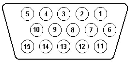
| PIN | SIGNAL |
| 1 | Setpoint #4 Output |
| 2 | Setpoint #5 Output |
| 3 | Setpoint #6 Output |
| 4 | Setpoint #7 Output |
| 5 | Setpoint #8 Output |
| 6 | Setpoint #3 Output |
| 7 | Setpoint #2 Output |
| 8 | Setpoint #1 Output |
| 9 | N/C |
| 10 | +3.3VDC |
| 15 | Digital Ground |
WEIGHT AVERAGING
The weight averaging option allows the scale to display an average weight taken from the platform over a specific time period. Readings are sampled from the platform forty times per second so a five second average would average 200 readings. Weight averaging can be setup to operate from a front panel key (the “8” key) or to operate on a continuous basis.
Push Button Operation
Pressing the EIGHT- key will start the average. While the average is being taken, the status bar on the bottom of the screen will display “Avg” and the graph bar will show the amount of time left. When the average is completed the result is locked on the display and the text “Loc” will be shown on the status bar. While the reading is locked the UNITS, NET/GROSS and other front panel keys will still operate as normal. To release the lock simply press the EIGHT-key again. While the average is being taken it can be aborted at any time by pressing the EIGHT-key.
Continuous Operation
When configured for continuous operation, constant averages at the selected time interval will be taken and locked on the display. The
text “Avg” will be shown on the status bar and the time progress shown on the graph line. The average key (the EIGHT-key) is used to
start and stop this process.
Configuring the Weight Average Option
The configuration parameters for the weight average option can be found in the menu SETUPMENU/OPTION SETUPS/WEIGHT AVERAGING. There are three settable options here.
Activate – ACTV: Activates or deactivates weight averaging.
Type of Averaging – TYPE: Push button or continuous operation.
Time of Averaging – TIME: Average acquire time can be set from one to sixty-three seconds.
KEY LOCK PASSWORD PROTECT
This key lock option adds the capability of disabling the front panel by having all of the function keys locked out, until a valid password
is entered. Once a valid password is entered, the keys will remain unlocked until the scale is powered down and powered up. By
default, the option is not active until an initial password is set.
Keypad Lock
- Press the menu button. Unlock keys by entering the current password, if necessary.
- Navigate to Options Setup and then scroll down to “Set Password”.
- “Enter new password” will appear on the display. Enter the desired password (4 digits long)
- Confirm the password by retyping the intended password. Confirmation is used to assure that a mistyped password is not stored.
Keypad Unlock
- Press menu button.
- “Enter Password” will appear on the top line of the display. Enter the password previously set.
- The function keys will remain unlocked until the scale’s power is powered down and powered up.
Deactivating Keypad Lock
- Follow the above procedure for setting the password.
- Instead of entering a password simply press enter twice.
- This will clear the password and deactivate the key lock option until the password is set again.
SPECIFICATIONS
| Series SAW-IS – Utilizing Intrinsically Safe SAW Load Cells | ||
| Model | Capacity & Resolution | Platform Size |
| S10 | 10 lb x 0.0001 lb / 4600 g x .05 g | 12″ x 12″ |
| S25 | 25 lb x .0002 lb /12 kg x 0.1 g | 12″ x 16″ |
| S50 | 50 lb x .0005 lb / 22 kg x 0.2 g | 12″ x 16″ |
| S100 | 100 lb x .001 lb / 45 kg x 0.5 g | 12″ x 16″ |
| S200 | 200 lb x .002 lb / 90 kg x 1 g | 12″ x 16″ |
| S200-L | 200 lb x .002 lb / 90 kg x 1 g | 20″ x 23″ |
| S500-L | 500 lb x .005 lb / 225 kg x 2 g | 20″ x 23″ |
| S500-XL | 500 lb x .005 lb / 225 kg x 2 g | 31.5″ x 31.5″ |
| S1000-XL | 1000 lb x .01 lb / 450 kg x 5 g | 31.5″ x 31.5″ |
| Power Requirements | 2600mAh NiMH AA cell (3 batteries) or 3.3VDC (through safety barrier) |
| Resolution | 1:100,000 |
| Repeatability | 1:100,000 |
| Typical Linearity* | 1:30,000 (Model Dependent) |
| Span Temperature Sensitivity | 5ppm/?C (5C-40C) |
| Creep | 20min (1:10,000) |
| Leveling | Adjustable |
| Tare Range/Zero Range | 100% Full scale |
| Electronics | All circuitry incorporated on one plug in board |
| Display | MKE-5-IS Intrinsically Safe LCD Graphics Display |
| Display Speed | Adjustable from .1 to six seconds |
| Overload Condition | Displayed warning at 102% of scale capacity. 150% by mechanical stops |
| Operating Temperature | 14F to 104F |
| Construction | Stainless steel platform cover, aluminum construction. |
| Controls | Units conversion, Net/Gross, Tare, Zero with secondary functions |
| Overall Dimensions | Model Dependent |
| Shipping Weight | Model Dependent |
| Options Available | Setpoints, USB, RS422, RS485 |
| Series SAW | |||||
| Model | SAW-X | SAW-T | SAW-L | SAW-C | SAW-H |
| Capacity x Readability | 10 lb x .0001 lb 5 kg x .05 g | 25 lb x .0002 lb 12 kg x 0.1 g | 50 lb x .0005 lb 25 kg x 0.2 g | 100 lb x .001 lb 50 kg x 0.5 g | 200 lb x .002 lb 100 kg x 1g |
| Readability | 25 mg | 50 mg | 100 mg | 250 mg | 1 g |
| Linearity* | 1:60,000 of full capacity | 1:60,000 of full capacity | 1:40,000 of full capacity | 1:40,000 of full capacity | 1:40,000 of full capacity |
| Response Time (avg) | 1 sec | 1 sec | 1 sec | 1 sec | 1 sec |
| Display Update | 0.4 sec. | 0.4 sec. | 0.4 sec. | 0.4 sec. | 0.4 sec. |
| Allowable Ambient Temperature | 10F…120F | 10F…120F | 10F…120F | 10F…120F | 10F…120F |
| Sensitivity Drift (15C-35C)* | approx.+/- 2 ppm | approx.+/- 2 ppm | approx.+/- 2 ppm | approx.+/- 2 ppm | approx.+/- 2 ppm |
| Overall Accuracy* | 1:20000 | 1:20000 | 1:20000 | 1:20000 | 1:20000 |
| Safe Overload | 500% | 500% | 500% | 500% | 500% |
| Power Consumption | 0.3 VA | 0.3 VA | 0.3 VA | 0.3 VA | 0.3 VA |
| Pan Size | 8″ x 10″ | 12″ x 16″ | 12″ x 16″ | 12″ x 16″ | 12″ x 16″ |
LIMITED WARRANTY
Note: Each scale comes with a visible or invisible tamper seal. If this seal is found to be broken or manipulated, the warranty is void.
Arlyn Scales warrants that your Arlyn Scales equipment and systems, when properly installed will operate per written specifications. All systems and components are warranted against defects in materials and workmanship for a period of one year.
Arlyn Scales warrants that the equipment sold hereunder will conform to the written specifications authorized by Arlyn Scales. Arlyn Scales warrants the equipment against faulty workmanship and defective materials. If any equipment fails to conform to these warranties, Arlyn Scales will, at their option, repair or replace such goods returned within the warranty period subject to the following conditions:
Upon discovery by Buyer of such nonconformity, Arlyn Scales will be given prompt written notice with a detailed explanation of the alleged deficiencies.
Individual electronic components returned to Arlyn Scales for warranty purposes must be packaged to prevent electrostatic discharge (ESD) damage in shipment.
Examination of such equipment by Arlyn Scales confirms that the nonconformity actually exists, and was not caused by accident, misuse, neglect, alteration, improper installation, improper repair or improper testing; Arlyn Scales will be the sole judge of all alleged non-conformities.
Such equipment has not been modified, altered or changed by any person other than Arlyn Scales. Arlyn Scales will have reasonable time to repair or replace the defective equipment. The buyer is responsible for shipping both ways.
In no event will Arlyn Scales be responsible for travel time, or on-location repairs, including assembly or disassembly of equipment, nor will Arlyn Scales be liable for the cost of any repairs made by others.
THESE WARRANTIES EXCLUDE ALL OTHER WARRANTIES, EXPRESSED OR IMPLIED, INCLUDING WITHOUT LIMITATION WARRANTIES OF MERCHANTABILITY OR FITNESS FOR A PARTICULAR PURPOSE. ARLYN SCALES WILL NOT, IN ANY EVENT, BE LIABLE FOR INCIDENTAL OR CONSEQUENTIAL DAMAGES
ARLYN SCALES AND BUYER AGREE THAT ARLYN SCALES SOLE AND EXCLUSIVE LIABILITY HEREUNDER IS LIMITED TO REPAIR OR REPLACEMENT OF SUCH GOODS. IN ACCEPTING THIS WARRANTY, THE BUYER WAIVES ANY AND ALL OTHER CLAIMS TO WARRANTY.
SHOULD THE SELLER BE OTHER THAN ARLYN SCALES, THE BUYER AGREES TO LOOK ONLY TO THE SELLER FOR WARRANTY CLAIMS.
NO TERMS, CONDITIONS OR UNDERSTANDING, OR AGREEMENTS PURPORTING TO MODIFY THE TERMS OF THIS WARRANTY SHALL HAVE ANY LEGAL EFFECT UNLESS MADE IN WRITING AND SIGNED BY A CORPORATE OFFICER OF ARLYN SCALES AND THE BUYER.
CONTROL DRAWINGS
The following drawings, required for the installation of the MKE-5-IS Scale System, are listed below and are included on the PDF version of this manual.
| Doc No | Title |
| 4010 | MKE-5-IS General Dimensions |
| 4013 | MKE-5-IS Intrinsically Safe Scale System, Installation and Wiring Diagram |
| 4011 | MKE-5-IS Indicator Label Drawing |
| 7213 | SAW-LC-08215 Load Cell Label Drawing |
| 7214 | SAW-LC-16033 Load Cell Label Drawing |
| 7334 | Approved SAW Load Cells Installation and Wiring Diagram |
