DC Solid State Relay – Wiring Diagram
[DOWNLOAD PDF]
This diagram shows how to wire the DC Solid State Relays to your system. Your system may come with 1 or more relays. In this example, a two relay box is used as an illustration. The other relays should be wired in a similar fashion. The diagram assumes customer supplied voltage of 24VDC but it can go up to 60VDC.
Note: These relays are NOT “dry contact” relays. They will not “short” at the output. They are designed for switching DC voltages only.
| SCALE SIDE (SETPOINT ACTUATOR) (J1) |
| 3V3 –Common voltage from Scale (Sink Configuration) |
| 1S –Setpoint Input 1 (Actuator for Relay # |
| 2S –Setpoint Input 2 (Actuator for Relay #2, if connected) |
| GND –Scale Ground Reference. |
| [DO NOT MODIFY WIRING ON THIS SIDE] |
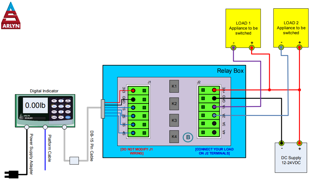
| LOAD SIDE (RELAY CONTROLLED OUTPUT) (J2) |
| +VE –Customer Sourced Power (Max 60VDC) |
| 1A –Output from Relay 1 |
| 2A –Output from Relay 2, if connected |
| Output from Relay 2, if connected…GND –Supply Ground |
| PROPRIETARY ARLYN SCALES, 59 2ndSTREET, EAST ROCKAWAY, NY 11518 |
|||||
| TITLE DC Solid State Relay Wiring Diagram (MAX 60VDC, 3.3A) |
|||||
| THE INFORMATION CONTAINED IN THIS DRAWING IS THE SOLE PROPERTY OF CIRCUITS AND SYSTEMS, INC. DBA ARLYN SCALES. ANY REPRODUCTION IN PART OR AS A WHOLE WITHOUT THE WRITTEN PERMISSION OF CIRCUITS AND SYSTEMS, INC. DBA ARLYN SCALES IS PROHIBITED. | DATE 04/10/2019 |
REVISED 10/26/2020 |
VERSION 2.10 |
DRAWN BY KARIM |
PAGE 1 OF 1 |
