Arlyn UpScale Touchscreen Indicator – User Manual
INTRODUCTION
Your New Scale
Congratulations on your purchase of an Arlyn Digital Scale. This Scale offers a combination of versatility, accuracy and simplicity in an easy to use and easy to maintain package. Advanced menu driven operating software, large memory capacity and an easy to use menu structure allows the scale to be configured for almost any application. To obtain the best performance and greatest utilization from your scale, read this instruction booklet completely and carefully
This Manual
This manual is divided into four parts:
| PART I | The first part (starting below) is the INSTRUCTION manual. It describes the general operation and the fundamental functions of the scale. This section also gives a general overview of some of the options that may come with the scale such as RS232, USB and Setpoints. |
| PART II | The second part of the manual is the OPTIONS Manual. This part of the manual describes all the potential options that come with the scale. It includes applications and instructions on how to use these functions. |
| PART III | The third part of the manual is the PREMIUM FEATURES Manual. This part of the manual describes extended functions of the Arlyn UpScale indicator using a conjunction of options equipped with the scale – such as User Management, Barcode Printing and Scanning, etc. These functions are still in ‘Beta’ and are provided “as is”. |
| PART IV | The fourth part of the manual is the WARRANTY part. This section describes the warranty provided with the scale as well as its limitations. |
PART I
1 FEATURES
|
|
2 PRECUATIONS
- Prevent inflammables and liquids from entering the scale head.
- Always use the included wall transformer when using AC outlet. NEVER replace the wall transformer with a plug. This could
cause electrical shock and severely damage to the scale. - Allow clearance on all sides of scale platform for accurate weighing.
- Do not drop large loads on scale platform.
- NEVER EXCEED THE RATED CAPACITY OF THE SCALE.
- Do not pull on the connecting electrical cables.
- Make sure that the scale and ramps are properly secured to the floor (most models).
- The scale’s power adapter must be connected to the proper grounded outlet. Avoid connecting the same power supply
circuit to large motors, or other similar equipment that might cause power supply voltage fluctuations. This will result in
fluctuating weights and unstable operation of the scale. - For Ultra-High Precision SAW Scales, the platform USB cable should never be hot plugged into the indicator when the
indicator is on. The indicator must be shut down before plugging in the USB platform connector.
3 BEST CONDITIONS FOR WEIGHING
- The scale should be level.
- Best operating temperature is about 68 degrees F.
- The weighing area should be kept clean and dry.
- The surface that the scale is resting on should be of solid construction and not prone to vibrations.
- Don’t install the scale near heater or air conditioner vents.
- Avoid drafts.
- Utilize a stable AC power supply. Avoid heavy motorized equipment on the same power line
- Do not operate the scale in close proximity of RF transmitters like cell phones and walkie-talkies.
- Warm-up the scale before use, or leave on “ready” mode.
4 INITIAL SETUP
4.1 Setup the scale as described in the following diagram
4.1.1 Setup for Strain Gage Scales (Regular Scales)
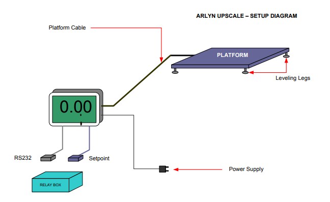
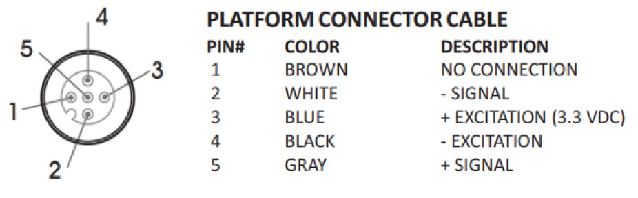
Platform Cable – Connects the PLATFORM to the INDICATOR through HDMI connector.
Power Supply – Connects the INDICATOR to your power outlet. Supplies power to the whole system
RS232 (Optional) – Connects to your PC/PLC RS232 connector.
Setpoint (Optional) – Connects to the Relay Box enclosure.
Relay Box (Optional) – Contains AC or DC Relays for controlling your system.
4.2 Ultra-High Precision SAW Scales
The Platform USB cable SHOULD NEVER BE HOT PLUGGED into the indicator. The USB is not meant to be connected or disconnected when the scale is powered up. If the scale is disconnected at any time (or whenever the message “USB DISCONNECTED” appears on the on the screen), the indicator must be shut down before plugging in the platform’s USB cable.
4.3 Platform Leveling Legs
Platforms will come with levelling legs that lifts the platform from the ground and provide the clearance for the internal load cell sensors to bend. At shipping, these leveling legs are screwed into the platform tightly (with no clearance) to protect the platform and the legs during shipping.
These legs MUST be unscrewed out to a certain point (NOT all the way that they fall off). The should be used to level the platform on the ground. Otherwise, the scale will not function properly.
4.4 Power up the Scale
Plug the micro-USB end of the power adapter into the indicator chassis, and the other end into 110-117VAC. This is the only way to power up the indicator after shutting down. Wait for the indicator to boot up until it shows the main weight screen. Press the ZERO button if the scale is not showing ZERO.
4.5 Stand-By and Shut Down
4.5.1 Special Note for Hardware Version A1209 and A1219
While the scale is running on AC Power (not on battery), the scale cannot be shut down. It can only go to “Stand By” mode. To shut the scale off completely, follow the sequence below:
- Unplug the power from the UpScale Indicator. This must be done to make the “Shut Down” option appear as a selection in the top right menu.
- Press the MENU button (3-dot icon at the top right corner of the screen). Notice that the “Shut Down” selection has now appeared. Press this option to shut down the indicator completely. Press “Grant” if a SuperUser Dialog box appears.
- To power the indicator up again, plug the power back into the indicator.
4.5.2 All Other Versions (including latest version A1218)
Press the MENU button (3-dot icon at the top right corner of the screen). Select the “Shut Down” option to shut the scale off. Press “Grant” if a SuperUser Dialog box appears
4.6 Multiple Indicators and Platforms
Indicators and Platforms must not be mixed and matched. Each indicator is calibrated towards a particular platform. If you purchased and received multiple scales, then each indicator must be matched with its own platform. To do this, match the serial number on the back of the indicator to the serial number on the platform. The platform’s serial number is usually located on the side of its frame or under it.
4.7 Test the Scale
Put a test weight on the platform and make sure the tablet indicator is reading the correct weight of the object.
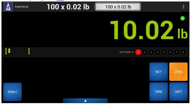
5 FRONT PANEL VIEW
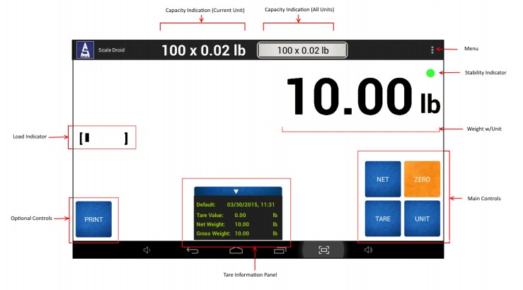
5.1 Non-Interactive
WEIGHT W/UNIT – Weight on the platform in the current unit setting
CAPACITY INDICATORS – Shows the capacity of the scale based on the current and all units
STABILITY INDICATOR – Shows the stability of the weight, based on automatic and user defined filters
NET INDICATOR – Shows the “net” indicator if in the scale is in net weighing mode
LOAD INDICATOR – Shows how much load is on the platform relative to its maximum capacity
TARE INFORMATION – Shows the information of the current tared weight, if any.
5.2 Interactive
MENU – For Settings and other options
MAIN CONTROLS – Shows the Main Control panel. Use this panel to perform main operations on the scale.
OPTION CONTROLS – Shows controls based on the options available on the scale
6 MAIN CONTROLS

| TARE | Pressing this key will tare any weight on the platform and switch the scale to the net mode. Holding this key down will clear any active tare weight. |
| NET/GROSS | Will toggle the indicator between the net and gross mode. The net mode will show the weight on the platform minus any tared weight. |
| UNIT | Pressing this key allows you to step through the various conversions. By default, the conversions available are pounds, kilograms, grams and ounces. There are four other conversions available that can be activated in the setup menu. This will add troy ounces, pennyweights, grains and a user defined conversion to the list. |
| ZERO | The fourth part of the Will zero the indicator is the WARRANTY part. This section describes the warranty provided with the scale as well as its limitations. |
7 COMMON OPTION CONTROLS
| Pressing this button will send a weight print in ASCII format through any Print Option available. This works for RS232, USB, Ethernet, Wireless Ethernet and Bluetooth. |
8 WIRED REMOTE BUTTON CONTROL
The Arlyn UpScale can be optionally quipped with an extension two-wire cable that can be used to “remotely” press any of the buttons mentioned in Main Controls (as well as PRINT and CYCLE buttons). This allows for significant convenience and applies some level of limited control of the indicator without actually being near it.
For this option, an additional two-wire, shielded cable would be coming out of the indicator. To activate the relevant button, the two wires need to be shorted together (a mere touch would do) to simulate a button press. An example of this is provided in the Remote Cycle Button section.
9 RS232 – QUICK OVERVIEW (optional feature)
9.1 Setup RS232
Connect the RS232 cable to your PC or PLC and setup the following Baud settings for Serial Port:
Baud Rate: 9600, Data Bits: 8, Parity: None, Stop Bit: 1, Flow Control: None
Press the PRINT button on the Front Panel to test the Print Function.
9.2 Using Terminal
Open HyperTerminal or RealTerm to communicate with the scale. Use the Serial COM port to connect to the scale using the parameters above. The following commands can be sent to the scale to perform certain actions
~*P*~ – To get the weight printed on your terminal.
Other supported commands are:
~*W*~- Get a JSON string for the weight
~*Z*~ – Zero the scale
~*U*~ – Switch unit
Read more on RS232 Communications Port
9.3 Using Sample PC App
Download our Arlyn UpScale – Wired Sample PC App at https://www.arlynscales.com/software-downloads/
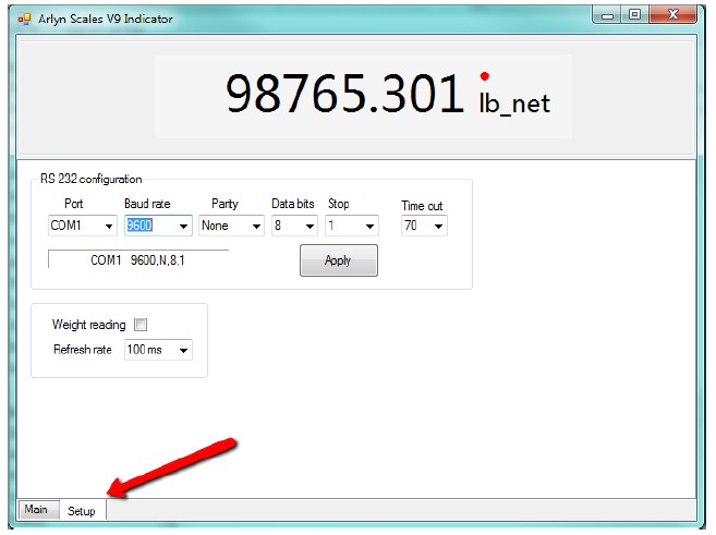
Unzip the resulting program and follow the instructions to install the V9 Indicator Program. Once completed, run the program. Press the Setup Tab to show the setup screen:
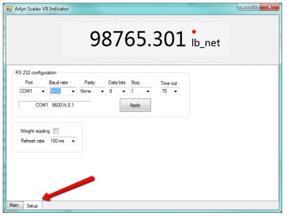
Make sure that the COM port selected matches the Serial COM port of your computer. The rest of the parameters need to match accordingly with the configuration set in your scale; Baud Rate: 9600, Data Bits: 8, Parity: None, Stop Bit: 1, Flow Control: None
Press APPLY button and go back to the Main Tab.
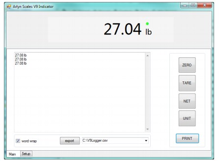
Press the PRINT button to get the scale date from the scale. Try the other buttons (ZERO, TARE, NET and UNIT) to see their effect on the scale.
Further information can be found at RS232 Communications Section under Test Software heading.
9.4 Print Format
By default, the scale is configured to print out a Weight with Unit. For example, if the weight is reading 50.00lb, pressing the PRINT key will send the weight in ASCII.
Example:
50.00 lb
Generic:
< WEIGHT > < UNIT >
Take note of the space character between weight and unit.
This is called the Print Frame. Different frame types can be selected to meet customer needs. For more information, read more on Print Frames.
*Multiple Platform Special Note*
For Multiple Platform configuration, the default Print Frame outputs the total sum of all platforms, as well as weights on individual platform. All the outputs reflect directly what is currently showing on screen. Here is an example of an output with two platforms.
Example:
08/09/2016 04:24:36, 35.2 lb, 25.0 lb, 10.2 lb, NA, NA
Generic:
< TIME AND DATE >, < TOTAL WEIGH T> < TOTAL UNIT >, < P1 WEIGHT > < P1 UNIT >, < P2 WEIGHT > < P2 UNIT >, < P3 WEIGHT > < P3 UNIT >, < P4 WEIGHT > < P4 UNIT >
Each item in the frame is delimited with a comma character and space character. The example shows “NA” notations in the last two slots. This is to show that those platforms are not available in this scale.
9.5 RS232 Impact Printers
10 USB – QUICK OVERVIEW (optional feature)
10.1 Setup USB
Connect the USB cable to your PC. Driver installation should be automatic for Windows 7 and later versions. For Linux/Unix environments, the computer needs to have FTDI/Prolific drivers available to interface with this USB scale. The USB connection on this scale evaluates as a Virtual Serial Port on any computer. Basically, all the operations available in the RS232 Overview section apply here as well.
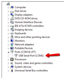
Once the driver has completed installation, check the Device Manager in Windows Control Panel to check which COM port has been assigned to the scale. In the image below, our scale has been assigned to COM 1.
10.2 Using Terminal
Open a terminal and connect to Serial Port as shown in your Device Manager screen. Set the following parameters in your terminal as default connection; Baud Rate: 9600, Data Bits: 8, Parity: None, Stop Bit: 1, Flow Control: None
The following commands are applicable.
~*P*~ – To get the weight printed on your terminal.
Other supported commands are:
~*W*~- Get a JSON string for the weight
~*Z*~ – Zero the scale
~*U*~ – Switch unit
Read more on USB Communications Port
10.3 Using Sample PC App
See Using Sample PC App section in RS232 Overview.
10.4 Print Format
By default, the scale is configured to print out a Weight with Unit. For example, if the weight is reading 50.00lb, pressing the PRINT key will send the weight in ASCII.
Example:
50.00 lb
Generic:
< WEIGHT > < UNIT >
Take note of the space character between weight and unit
This is called the Print Frame. Different frame types can be selected to meet customer needs. For more information, read more on Print Frames.
*Multiple Platform Special Note*
For Multiple Platform configuration, the default Print Frame outputs the total sum of all platforms, as well as weights on individual platform. All the outputs reflect directly what is currently showing on screen. Here is an example of an output with two platforms.
Example:
08/09/2016 04:24:36, 35.2 lb, 25.0 lb, 10.2 lb, NA, NA
Generic:
Each item in the frame is delimited with a comma character and space character. The example shows “NA” notations in the last two slots. This is to show that those platforms are not available in this scale.
11 SETPOINT – QUICK OVERVIEW (optional feature)
The scale has been setup to turn on Setpoint 1 if the weight is greater than 10lbs. To test this, place a weight greater than 10lbs on the scale. The scale will sound a tone and light up (1) on the Setpoint Indicator array.
11.1 Enhanced Setpoint Functionality
Setpoint Print – You can also setup the Setpoint Controller to print out a weight frame at certain target weights. This is possible if your scale equipped with any of the print options (RS233, USB, Ethernet, Wi-Fi, etc.)
Setpoint Email – You can setup the Setpoint Controller to email out a weight frame at certain target weights. This is possible if your scale is equipped with Ethernet or Wi-Fi (paid options).
Read more on Setpoint Operation here.
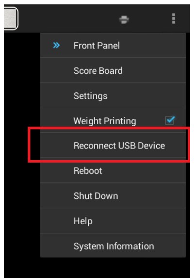
12 QUICK MENU ITEMS
The Front Panel Menu items can be accessed using the Top Right menu button near the button indicator.
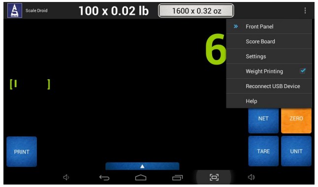
FRONT PANEL – Directs you back to the Front Panel screen
SCORE BOARD – Shows the Weight screen with large weight letters and minimal controls
SETTINGS – Shows the Settings screen where main and optional parameters can be configured
[OPTION TOGGLE] – Some options can be toggled right on the Quick Menu
RECONNECT USB DEVICE – Mostly used for troubleshooting purposes.
Page | 16
HELP – Shows the help screen (Currently not active)
The Quick Action menu will have additional items depending on options available on your scale. It provides a convenient method of jumping to frequently used operations.
13 SYSTEM OPERATION
13.1 General User Interface
The display is a user-friendly, touchscreen interface with quick access to common functions that you would use on a day-to-day basis. Right on the Front Panel, you have access to the Main Controls and the Quick Menu Items. If your scale is equipped with options, then you might find some additional items on the Front Panel. Some of them are listed under Common Option Controls. The Quick Menu Items will allow you to access the inner workings of the scale such as Tares, Platform Management, System Setup,
Diagnostics, etc.
Some of these settings will be described under this section. Other more advanced settings will be described in later versions of this manual. However, unless absolutely necessary or unless directed by a scale technician, try not to play with the advanced settings of these scale. You will run the risk of temporary or permanently disabling it.
13.2 Tares
The quickest way to use the Tare function is by utilizing the TARE key on the Front Panel. Pressing this key will tare any weight on the platform and switch the scale to the net mode. Holding this key down will clear any active tare weight.
13.2.1 Working with Tare Definitions
A more accurate and convenient way to tare weights is to define and store them in memory. You may define as many tares as you like within the scale’s memory capacity. Your scale has up to 4GB of storage available, providing virtually unlimited space for saving tares and other data.
Once you have a list of tares saved in memory, you may activate any one you like, zero the platform and begin counting. These tares remain permanently in memory even when the power is removed.
*Multiple Platform Special Note* – If you have multiple platforms, then you can activate one tare per platform, allowing you to perform parts counting across all connected platforms concurrently.
There are a number of functions used when working with tares in memory. They are:
- Creating a new, default tare.
- Editing its value (piece weight).
- Changing its description.
- Activating it.
- Deleting unneeded tares.
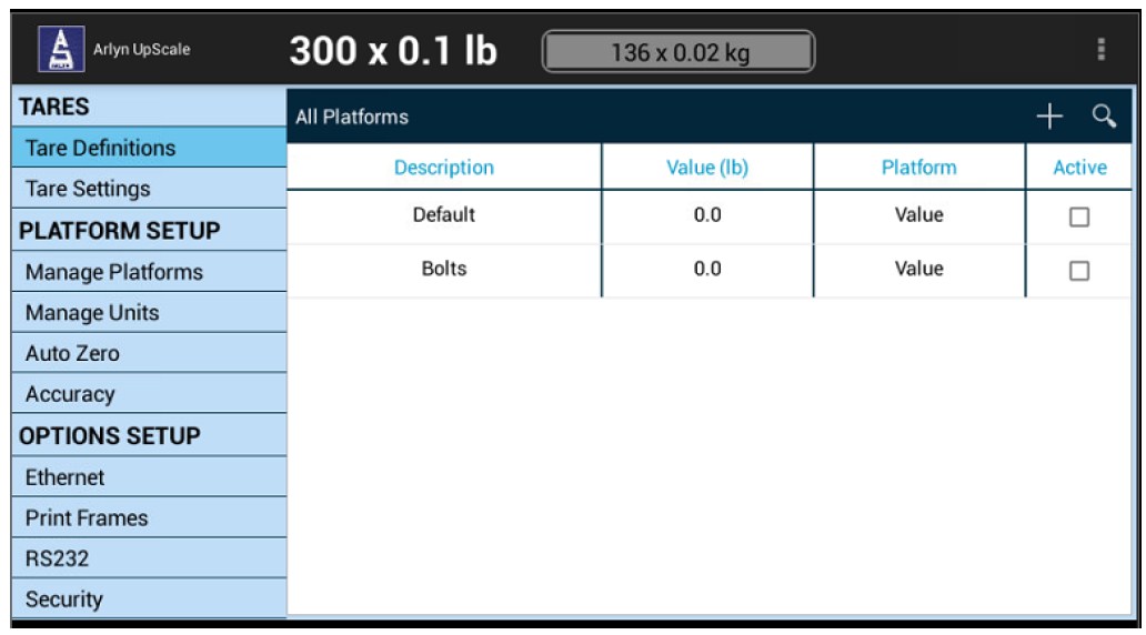
13.2.1.1 VIEW STORED TARES
To view the currently stored tares:
- Touch the QUICK MENU button and go to “Settings” to enter the scale’s Setup Menu.
- Touch and Drag the left panel downwards to show the Tares section. Then touch the “Tare Definitions” selection.
- You will be shown a list of all tares that are currently saved in memory. If there are none then “None Defined” will be shown. See below
13.2.1.2 CREATING A NEW TARE
To add a new tare to the list, touching the “+” icon on the top right corner of the Screen to open the New Tare Definition dialog box.
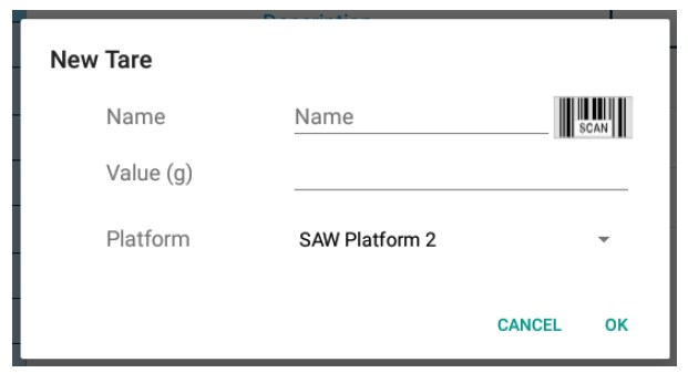
13.2.1.2.1 The New Tare Dialog
The New Tare Dialog Box will show a set of fields that need to be filled to create a new tare in memory.
13.2.1.2.2 Field Definitions
| NAME | TYPE | DESCRIPTION |
| Name | Text (Required) | Enter the name of the Tare definition so you can easily find it in the table. If your indicator is equipped for barcode scanning, use the Barcode Scan button to scan an existing Tare name into the field. |
| Value | Decimal (Required) | The weight of the tare. This can be entered directly if you know the weight of the tare. |
| Platform | Selection | *Multiple Platform Special Note*. You can select for which platform this tare is associated with. When this tare is activated, it only activates this tare for that platform. Please note that only one tare can be activated per platform. |
13.2.1.3 ACTIVATE A SAVED TARE
Now that you have created a new tare, how do you use it? You will need to “activate” the tare in the Tare Definitions List to start using that part for counting.
In the Tare Definitions list, look at the tare record you want to activate and look for the “Actv” field. You may have to scroll the table horizontally to find the field. See example below.
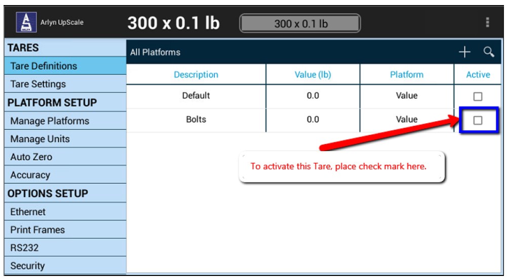
That’s it. Your tare has now been activated. Use the QUICK MENU to get back to the Front Panel screen. You are now ready to do some Parts Counting.
13.2.1.4 SEARCHING FOR A TARE
If you have too many tares defined in the Tares Definition List, it is going to be difficult to scroll through hundreds of records to look for the tare you are trying to activate. The Arlyn Upscale User Interface framework implements a Search system that allows you to
search through the records using ID Code, Part Number or Description. To begin your search, click on the Search Icon and text field will open up to begin your search. The searching mechanism is instantaneous, meaning, as soon as you start typing, on the third letter the system will start filtering out your results.
13.2.1.5 EDITING A TARE
You can edit a tare by simply touching the associated tare record. A dialog box equivalent to the New Tare will appear, except with all the fields filled in.
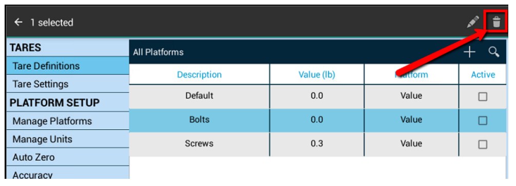
13.2.1.6 DELETING TARES
To delete an unneeded tare from the Tares Definitions List,
-
- Touch and Hold the tare record you would like to delete. The tare now is permanently selected. At this point, you can also select more Tare records you wish to delete.
- Take a look at the top right corner of the screen, a new set of icons have appeared. Notice the “Trash Can” icon. That is the delete button.
-
- Touch the “Trash Can” icon to delete the tare from the list. The following message is displayed at the bottom of the screen. “1 Tare Deleted | Undo”
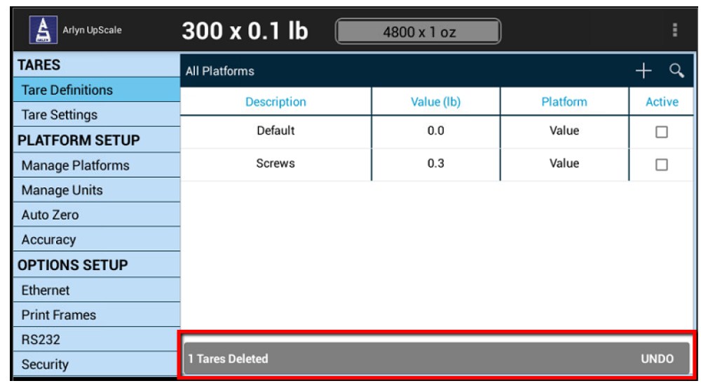
- What if you made a mistake deleting a Tare or Tares? The Scale gives you one last chance to get them back again. Touch the Undo button to restore all your records back to your Tare Definitions List. This can only be done if you have not moved away from this screen.
13.2.2 Tare Settings
The Scale System provides a way to change the behavior of Tare weights when it comes to how some options interpret it. For example, for Analog Output 4-20mA, you can set the scale so that the 4-20mA will respond to Gross Weight or Net Weight. Or you can set the scale to remember the Tare weight you set last before you shutoff the scale.
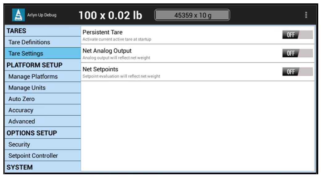
13.2.2.1 PERSISTENT TARE
Turn on Persistent Tare if you want the scale to remember the last Tare you set. This works for QuickTares from the Front Panel as well as Activated Tares from the Tare Definitions Screen.
13.2.2.2 NET ANALOG OUTPUT
Turn on Net Analog Output if you want the 4-20mA to reflect the Net Weight shown on the screen. Otherwise, leave it in the OFF position for default operation (4-20mA will reflect the Gross Weight only).
13.2.2.3 NET SETPOINTS
Turn on Net Setpoints if you want the Setpoint to evaluate Net Weights instead of Gross Weights. Otherwise, leave it in the OFF position for default operation (Setpoints will reflect the Gross Weight only).
13.2.3 Special Function: Import/Export Tare Definitions
The Arlyn UpScale can be equipped to allow import and export of Tares, Samples or Setpoint Definitions. This is only available for scales equipped with USB Data Logging Option. For further information, please see the section for “Import/Export of Database Definitions” in USB Data Logging.
13.3 Platform Setup
The Scale System revolves around one or more Platform Definitions that are configured and stored in memory. Most scales have only one weight platform. Each platform is fully configurable depending on the type of scale. If the scale is not an NTEP (Legal for trade), then there is a lot more freedom in configuring the platform. Some configuration parameters are scale capacity, displayed resolution, filtering, calibration and many other parameters which will be outlined in detail below. To access Platform Setup from the Front Panel, touch QUICK MENU->SETTINGS->MANAGE PLATFORMS.
13.3.1 Platform Management
The following screen lists all the platforms connected to the scale. As mentioned before most scales will have only one weight platform connected. This screen shows two platforms connected for informative purposes only.
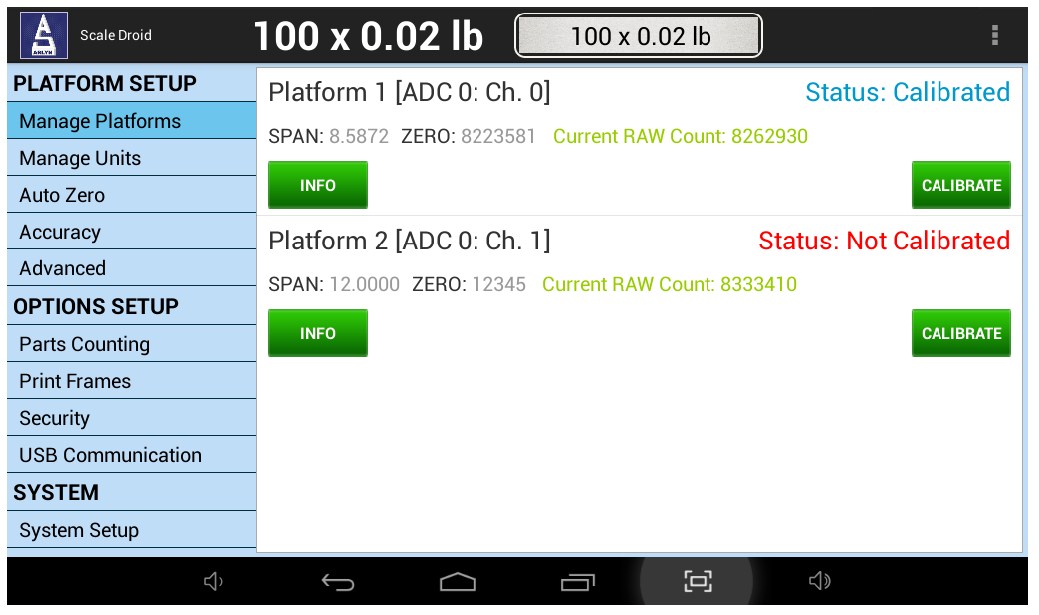
Each Platform Definition displays some Platform properties to better inform you about the operational condition of the scale.
| Platform Name | Displays the name of the platform. In the screenshot above, “Platform 1” is the name of the first platform connected to the display. “Platform 2” is the second platform connected to the display. This name can be changed under the “Info” panel |
| Platform Channel | Displays which channel the platform is connected to. In the above screenshot, Platform 1 is designated to [ADC 1: Ch. 0]. This means it is connected to A/D Converter #1 on Channel 0. Definitions for “A/D Converter” and “Channel 0” are beyond the current scope of this manual. |
| Status | If you have performed a calibration and completed to the end, the status will show “Calibrated”. This doesn’t mean that the calibration is proper. You can only determine if the calibration is proper by weighing known weights. |
| Span | Shows the Span Constant for the current platform connected. This will only change if a new calibration is performed. |
| Zero | Shows the Zero Constant for the current platform connected. This will only change if a new calibration is performed. |
| Current RAW Count | Shows the current load cell count being fed into the analog to digital converter (A/D Converter). If the last two digits are the only digits changing rapidly, it means the platform is in working condition. It’s not good if all the numbers are changing or if it is completely static. Also, pushing the platform will increment this number. |
13.3.1.1 PLATFORM INFORATION
To change the name of the platform or to view the configured capacity, resolution other properties of the platform, touch on the INFO button to view the properties of the platform.
13.3.1.2 PLATFORM CALIBRATION
Calibration is used to set the Zero and Span values of the scale so that it reads correctly. Technically, calibration is a process that sets the lowest raw count reading from the platform to a Zero Condition (when the platform is empty) and adjusts the internal gain of the platform so that it associates the highest raw count reading to the full capacity.
To start the procedure, press the CALIBRATE button on the Platform definition. This process conveniently leads you through a Wizard for calibrating the platform. There is very little chance to perform an improper calibration if the process is completed by following what the instructions tell you in this wizard.
CALIBRATION TYPES
Full or Span Calibration is used to set the internal gain of the indicator so that it reads correctly. A calibrated weight is needed to perform Span Calibration. Any weight maybe used within the capacity range of the scale. A minimum weight of 10% of full capacity is needed. A weight of 50% of capacity is recommended. Using weights less than 10% of capacity is not recommended and may lead to improper calibration.
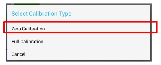
If your Platform Type is a Strain Gage scale, then you should never use Zero Calibration. Zero Calibration is only used for Ultra Precision SAW Platforms. Platform Type can be determined using the INFO button.
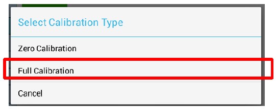
FULL (SPAN) CALIBRATION (For Strain Gage and SAW Scales) – Select Full Calibration from the Calibration Type dialog box
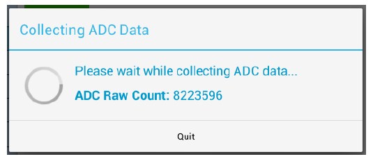
STEP 1: Remove all weight from the platform and touch NEXT.
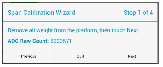
The next dialog shows that the Scale System is now collecting data from the platform. Wait for this process to complete. If it is taking exceptionally long (more than 2 minutes), then press the QUIT button and start the calibration process again.
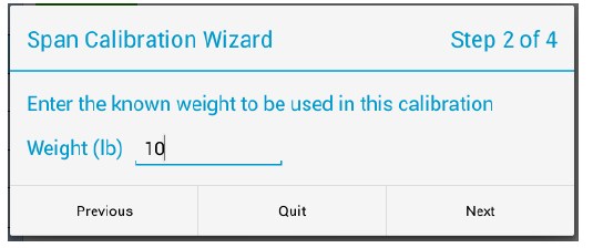
STEP 2: Enter the known weight you will be using for this calibration. Then touch NEXT. When using a known weight, please follow the guidelines as outline under the section for Span Calibration.
STEP 3: Now place the known weight on the platform and then touch NEXT as instructed by the following screenshot.
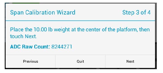
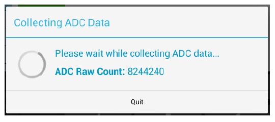
Wait for the Scale System to collect the data for the known weight.
STEP 4: The Full Span Calibration is now complete. Press the FINISH button. Then go to the Front Panel and make sure the current weight shows the value of the test weight you just used for calibration.
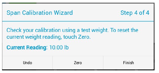
If the Front Panel is showing a value other than the test weight, remove the test weight from the platform, then press the ZERO button, and then try placing the test weight again on the platform.
ZERO CALIBRATION (For Ultra Precision SAW Scales only)
*PLEASE NOTE* Do not perform this calibration for Regular Strain Gage scales. This could erase your current calibration
It is highly recommended to perform zero calibration after the arrival of the SAW Scale at the customer’s location. This will enable the scale to acclimatize with the customer’s environment and provide the customer with the most accurate readings during its operation.
This procedure does not require any calibration weight. It takes only few minutes to perform. Make sure the platform is empty. Then select “Zero Calibration” from the “Select Calibration Type” dialog.
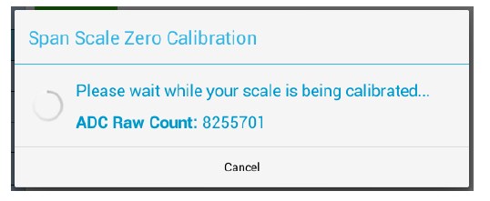
The scale will now try to calibrate the Zero Condition of the platform. You may cancel this operation at any time, however, you may have to start the process again.
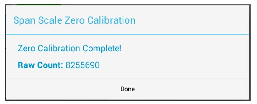
Once the process completes, a dialog box like the screenshot below will appear. Just touch DONE and proceed to test the scale functionality.
13.3.2 Manage Units (TBD)
13.3.3 Auto Zero
Auto Zero determines how the platform will zero on power up. The following selections apply.
| Auto Zero | With this option selected, the scale will automatically zero out any weight on the platform. This is a good option for environments not prone to power failures. Also, it is a great option if you always want to start the scale at zero regardless of what the state of the platform (loaded or unloaded). |
| Last Zero | At initialization, the scale will zero out the platform to the last preserved zero state when the ZERO button was pressed. This means that the scale remember the last time the ZERO button was pressed. This results in the remembering the value of the weight currently on its platform when the scale is shut off. In addition to that, suppose the weight was changed after the scale was shut off, the next time the scale is turned out, it will show the new weight. This is an excellent option for environments prone to power failures. It is also an excellent option if you need to constantly monitor the weight on the platform without interruptions. |
| None | The scale will initialize the platform based on its previous state. It is not a recommended to leave the scale in this option. The scale may start up with an unknown state. |
13.3.4 Accuracy
Sometimes the scale needs to work in a non-stable, noisy environment such as on a moving truck or vibrating floor or surface. For these environments, additional weight filtering process needs to take place to give you a more stable reading. The scale software engine provides several features to help in getting a better readability out of the scale such as Zero Tracking, Software Filter, Stability Control and Motion Detect. The settings for these features are entirely up to you. Arlyn cannot provide the best parameters for you because each scale operates in a unique environment. You will need to study the scale’s behavior over time and make changes to the parameters accordingly. In the explanation below, this manual will go over some real world examples to give you hints on how to study the scale behavior to set these parameters.
13.3.4.1 ZERO TRACKING
A scale sitting for long periods of time without weight on the platform is prone to drift from zero due to temperature changes and a number of other factors. Generally this is not a problem and you can press the ZERO button to return the reading to zero before weighing. Zero tracking, when enabled, will detect small reading changes over time and correct the platform back to zero.
| Active | Activates or deactivates Zero Tracking. |
| Window | This is the range above or below the current ZERO point that needs to be continuously compensated (up to 20% of full capacity) to correct zero shift. For example, over two days, you notice that the scale has shifted in weight by 0.2lbs, even though there is no weight on the platform (and was originally reading perfect 0) or a weight that was constant over two days is now reading 0.2lbs over. This is known as “Zero Shift” and can be corrected using Zero Tracking. After studying the scale’s behavior on this aspect, we can plug this 0.2lb range in this Window field. Now you will notice that your scale will zero out any deviations that falls within ±0.2lbs. |
| Noise Count | Sometimes, the scale will produce spikes that may fall within the window range. These spikes may be the result of electrostatic discharge, or some electrical noise within the environment. They are extremely momentary and may only last a couple of milliseconds. This becomes problematic because we don’t want the scale to perform zero tracking just because the scale produced a spike. So the noise count is the number of consecutive weight readings to finally determine if a shift has occurred. Set this to a reasonable number (such as 3 readings). Taking the example detailed in “Window”, if the scale detects the 0.2lbs shift in 3 consecutive readings, it will take corrective action. |
13.3.4.2 SOFTWARE FILTER
The raw internal reading from the load sensor contains electronic noise and other factors that can cause the reading to be drifty and non-repeatable. All electronic scales incorporate some sort of filtering to compensate for this. Another use for filtering is to help stabilize a scale when it is used on a surface that is vibrating, in windy conditions, when subjected to RF interference or when used on a noisy power line. Your scale has two stages of filtering. The first is an electronic filter that is permanently enabled and the second is the software filter which is fully configurable.
In general, a low degree of filtering will cause the scale to be quick to react but prone to noise and vibrations. Heavy filtering will eliminate the noise and vibrations but the platform will react slowly to changes in weight. We have by default set up the optimum filtering parameters for general use. These should only be changed in extreme circumstances.
There are four settable options on the setup screen.
| Active | Activates or deactivates Software Filter. |
| Buffer | These are the number of averaging slots in the software filter. The higher this number, the slower the filtering process, the more accurate the weight reading. |
| Window |
Set’s the weight value window at which you want the filtering to take place. The standard value for this field could be the scale’s resolution. So if your scale is at a resolution of 0.02 lb, then set that value to this window. By default, the value has been set in factory. If you set a lower value than the resolution of the scale, then the scale will be stricter in its filtering and almost all values from the platform will be hitting the noise count giving you a much slower performance. Set a higher value and the scale will be more lenient in its filtering allowing more noisy values to pass through for processing giving you a better performance but higher inaccuracy in readability. The best way to approach this window is determine the range of fluctuation with the default setting. For example, by observing the scale, you notice that your scale is varying by 1lb. If that is the case, then set the value here to 1lb. You will then get stable readings within this range. |
| Noise Count | This is the noise count of filtering mechanism. This sets the number of weight values that need to be discarded before considering that the new weight value is a new value and not part of the current weight value averaging process. The higher this number, the less accurate the weight value, the faster your performance |
13.3.4.3 STABILITY CONTROL
If the scale display values are not stable due to a noisy or unstable environment and you do not want to estimate the actual value of the weight on the platform, the scale can estimate it for you.
Stability Control is not by any means a filtering mechanism. This feature should only be used if you know that the scale will always be unstable or in constant noise. What this feature does is lock in an appropriate weight based on the stability count and a stability window you have specified in this screen. The weight locked, may not be the most accurate weight of the object placed on the platform, but it is a best guess as computed by the Stability Control in this scale. Once the stability lock has been placed, the lock will not be removed until the platform experiences a weight change greater than the stability window.
There are four settable options on the setup screen.
| Active | Activates or deactivates Stability Control. |
| Source | This sets the primary source of readings that the Stability Control mechanism will use to estimate the best lock-in weight. There are two selections here. |
| A/D Reading | This selection makes the Stability Control mechanism take readings unfiltered and straight from the load cell. This is the fastest and the least complex selection and therefore the default. |
| Filtered | This selection is an advanced selection. With this selection, Stability control uses filtered weights based on parameters set by the Software filter. Selecting this option automatically activates software filter. Make sure the parameters in Software filter are properly set or the scale will behave erratically. Use this selection only if you know what you are doing. |
| Window | The Window field operates similarly as explained in the Software Filter section. |
| Count | This number indicates the number of stable readings within the window set above to qualify a lock in. Suppose this number is set to 3, then the Stability Control mechanism will try to read 3 readings consecutively that are within the window above. If they fall within that window, then the weight will lock in, else, it will reset and start over until it gets 3 stable readings. |
After Stability Control is activated, an unfilled square appears at the bottom left of the screen during normal weight readings. While the scale does not have a stable reading, the square will appear unfilled. As soon as a weight has been found, it will lock this weight and the square will be filled. Once the lock has been obtained, the reading will not budge until a weight change greater than the window set has occurred.
13.3.4.4 ZERO/MOTION DETECT
This scale can detect if there is motion on the platform and/or if the platform is at zero. This feature does not process, control or filter the scale weight reading in any way. It is there for determining if the given weight reading has a property of motion or zero. There are four settable options on the setup screen. The first three are for the Motion Detect setup. The fourth option controls the zero indicator on the main display. These menu items are as follows:
| Active | Activates or deactivates motion detection. |
| Motion | The Motion field determines the range of weight at which you want to define “motion”. So if the scale has been set on a moving truck, and you have determined that the scale always is within a certain weight range when the truck is moving normally at normal speeds, you would want to set the Motion window at that range. For example, say you have put a weight on the scale that would read 20lbs on a stable surface. But on the truck it reads 18-23lbs. This means that your motion window is 5lbs. So now you know that you want to detect motion if and only if it is greater than 5lbs, so you can set the Motion window to 5lbs. |
| Time | This works along with Motion Window to detect a stable reading. The reading must be stable within the motion window for this length of time (in seconds) in order to be considered a stable reading. As long as the weight remains within specified motion window within this time, the scale would confirm that there is no motion detected. If the weight jumps out of the motion window, then the scale would register as “Motion Detected” and reset the time interval. |
| Zero Window | This controls how close the scale needs to be to the true zero point before lighting the zero indicator (ZR) on the bottom of the main display. For example, if you set the window to 1lb, then any weight from 0lb to 1lb will register as ZR (meaning ZERO condition). |
| Noise Count | This sets the noise count of the detect mechanism. This sets the number of weight values that need to be discarded before considering that the new weight value is a new value and not part of the current weight value averaging process. The higher this number, the less accurate the weight value, the faster your performance |
After ZERO/MOTION DETECT is activated, go back to the Front Panel home screen and notice a tiny square indicator appears at the right of the screen near the bar graph. If the platform is moving, the square indicator turns into a 4-arrow indicator will show as it is seen here. If the platform is within the bounds of ‘No Motion’ as set here, then the tiny square indicator appears again.
Note: The Motion/Detect feature is always turned on (even though it may show deactivated). This facilitates in showing the stability indicator on the top right corner of the weight.
14 CALIBRATION AND TROUBLESHOOTING
Your scale has been precisely calibrated at the factory before shipping. It has the capability to adjust its own calibration to a certain degree to compensate for aging electronics, and temperature changes. This being the case, it is possible that you will never have to
calibrate the scale. Doing so may leave you with a worse calibration than you started with. Does your scale really need to be calibrated? If so what steps are needed? Follow the steps outlined below to help make this determination.
Scale Calibration is described in the Platform Calibration section.
14.1 Scale reads zero and will not move.
- Make sure that any and all shipping screws are removed from the platform.
- On platform scales, check that all four level legs are contacting solidly against the floor.
- If level legs are screwed in all the way then the stud from the level leg may be contacting the underside of the platform not allowing the load sensor to flex.
14.2 Scale reading is fluctuating wildly.
- Scale must be on a non-vibrating surface. Breezes may affect scales of lighter capacities.
- Scale must be installed on a clean power line. Electric motors, computers or any other devices can cause power line interference.
- RF interference can cause scale readings to fluctuate. Are there any transmitters nearby like cell phones or walkie-talkies?
- If the scale is a remote platform type, check to see if the cable from the platform to the indicator in plugged in properly. If so, then remove the plug temporarily to check for bent or missing pins.
- Check for nicks or cuts on the platform cable.
14.3 Scale reading is different on different areas on the platform?
- On platform scales, check that all four level legs are solid against the floor. If a level leg is screwed in all the way then the stud from the level leg may be contacting the underside of the platform not allowing the load sensor to flex.
- Check for any mechanical interference. Is there anything rubbing against the platform?
14.4 Scale corners properly but does not indicate the correct weight.
- On platform scales check that all four level legs are solid against the floor.
- Check for any mechanical interference. Is there anything rubbing against the platform?
- Perform span calibration.
14.5 Platform Connector Pinout (Not for Ultra Precision SAW Scales)
14.6 Options Setup
This section is detailed in another part of the manual. The section thoroughly describes each and every option that may or may not come standard with the scale. Proceed to the Options Setup for further details.
15 SPECIFICATIONS
15.1 Strain Gage Regular Precision Scales
15.1.1 Available Models
| Model | Capacity | Resolution | Platform Size* |
| 620V/820V | 5lb / 2.2kg | 0.001lb \ 0.0005kg | 12″ x 16″ |
| 620X/820X | 10lb / 4.5kg | 0.002lb \ 0.001kg | 12″ x 16″ |
| 620T/820T | 25lb / 11kg | 0.005lb \ 0.002kg | 12″ x 16″ |
| 620L/820L | 50lb / 22kg | 0.01lb \ 0.005kg | 12″ x 16″ |
| 620C/820C | 100lb / 45kg | 0.02lb \ 0.01kg | 12″ x 16″ |
| 620F/820F | 150lb / 67kg | 0.05lb \ 0.02kg | 12″ x 16″ |
| 620G | 300lb / 136kg | 0.1lb \ 0.05kg | 9.25″ x 9.25″ (or 14″ x 14″) |
| 320D | 500lb / 226kg | 0.1lb \ 0.05kg | 20″ x 27″ (Other sizes avail.) |
| 320M | 1,000lb / 453kg | 0.2lb \ 0.1kg | 20″ x 27″ (Other sizes avail.) |
| 5-4405 | 5,000lb / 2260kg | 1lb \ 0.5kg | 4′ x 4′ (Other sizes avail.) |
| 5-4410 | 10,000lb / 4536kg | 2lb \ 1kg | 5′ x 7′ (Other sizes avail.) |
| 5-4420 | 20,000lb / 9072kg | 5lb \ 2kg | 7′ x 9′ (Other sizes avail.) |
*Other Platform sizes are available on request.
15.1.2 Other Specifications
| Power Requirements | 117-220VAC +/- 10% 50/60 Hz (or 24VDC if equipped) (Included with DC Adapter) |
| Current Consumption | (MKE-5 Indicator + Platform) Approx. 0.1A (Platform only) Approx. 10mA |
| Accuracy | 0.1% of full scale0.1% of full scale |
| Leveling | Adjustable |
| Tare Range/Zero Range | 100% Full scale |
| Electronics | All circuitry incorporated on one plug in board |
| Display | Arlyn UpScale Touchscreen Display |
| Display Speed | Adjustable from .1 to six seconds |
| Overload Condition | Displayed warning at 102% of scale capacity. 150% by mechanical stops |
| Operating Temperature | 14F to 104F / -10C to 40C (for Platform only) |
| Construction | Models 620 & 820-Stainless steel platform cover, aluminum construction. 5-4405-Diamond plate steel. Aluminum or stainless steel is optional. Model 320 aluminum. Stainless steel is optional. |
| Load Cell | Stainless steel construction for reliability (most models) |
| Controls | Units conversion, Net/Gross, Tare, Zero with secondary functions |
| Overall Dimensions | 13″ W x 16″ D x 1.5″ H (620/820), 20″ W x 27″ D x 1.5H (320), Depends on model ordered (5-4405) |
| Shipping Weight | 21 lbs. (620/820), 30 lbs. (320), Depends on model ordered (5-4405) |
15.2 Ultra-Precision SAW Scales
15.2.1 Available Models
| Model | Capacity & Resolution | Platform Size* |
| SAW-X | 10 lb x 0.0001 lb / 4600 g x .05 g | 12″ x 12″ |
| SAW-T | 25 lb x .0002 lb /12 kg x 0.1 g | 12″ x 12″ |
| SAW-L | 50 lb x .0005 lb / 22 kg x 0.2 g | 12″ x 12″ |
| SAW-C | 100 lb x .001 lb / 45 kg x 0.5 g | 12″ x 12″ |
| SAW-H | 200 lb x .002 lb / 90 kg x 1 g | 12″ x 12″ |
| SAW-HL | 200 lb x .002 lb / 90 kg x 1 g | 20″ x 23″ |
| SAW-JL | 300 lb x .002 lb / 135 kg x 1 g | 20″ x 23″ |
| SAW-KL | 500 lb x .005 lb / 225 kg x 2 g | 20″ x 23″ |
| SAW-KXL | 500 lb x .005 lb / 225 kg x 2 g | 31.5″ x 31.5″ |
| SAW-MXL | 1000 lb x .01 lb / 450 kg x 5 g | 31.5″ x 31.5″ |
*Other Platform sizes are available on request.
15.2.2 Other Specifications
| Power Requirements | 117-220VAC +/- 10% 50/60 Hz, 2A (Included with DC Adapter) |
| Current Consumption | (MKE-5 Indicator + Platform) Approx. 0.1A (Platform only) Approx. 50mA |
| Accuracy | 0.01% of Full Scale |
| Resolution | 1:100,000 |
| Repeatability* | 1:100,000 |
| Linearity* | 1:60,000 (Model Dependent) |
| Span Temperature Sensitivity* | 5ppm/?C (5C-40C) |
| Creep* | 20min (1:10,000) |
| Leveling | Adjustable |
| Tare Range/Zero Range | 100% Full scale |
| Electronics | All circuitry incorporated on one plug in board |
| Display | Arlyn UpScale Touchscreen |
| Display Speed | Adjustable from .1 to six seconds |
| Overload Condition | Displayed warning at 102% of scale capacity. 150% by mechanical stops |
| Operating Temperature | 14F to 104F (for Platform Only) |
| Construction | Die-cast Aluminum Frame, stainless steel weighing pan and click-type switches. |
| Controls | Units conversion, Net/Gross, Tare, Zero with secondary functions |
| Overall Dimensions | Model Dependent |
| Shipping Weight | Model Dependent |
| Series SAW | |||||
| Model | SAW-X | SAW-T | SAW-L | SAW-C | SAW-H |
| Capacity x Readability | 10 lb x .0001 lb 5 kg x .05 g | 25 lb x .0002 lb 12 kg x 0.1 g | 50 lb x .0005 lb 25 kg x 0.2 g | 100 lb x .001 lb 50 kg x 0.5 g | 200 lb x .002 lb 100 kg x 1g |
| Readability | 25 mg | 50 mg | 100 mg | 250 mg | 1 g |
| Linearity* | 1:60,000 of full capacity | 1:60,000 of full capacity | 1:40,000 of full capacity | 1:40,000 of full capacity | 1:40,000 of full capacity |
| Response Time (avg) | 1 sec | 1 sec | 1 sec | 1 sec | 1 sec |
| Display Update | 0.4 sec. | 0.4 sec. | 0.4 sec. | 0.4 sec. | 0.4 sec. |
| Allowable Ambient Temperature | 14F to 104F | 14F to 104F | 14F to 104F | 14F to 104F | 14F to 104F |
| Sensitivity Drift (15C-35C)* | approx.+/- 2 ppm | approx.+/- 2 ppm | approx.+/- 2 ppm | approx.+/- 2 ppm | approx.+/- 2 ppm |
| Overall Accuracy* | 1:20000 | 1:20000 | 1:20000 | 1:20000 | 1:20000 |
| Safe Overload | 250% | 250% | 250% | 250% | 150% |
| Power Consumption | 0.3 VA | 0.3 VA | 0.3 VA | 0.3 VA | 0.3 VA |
*Typical
PART II
Options Setup
16 OPTIONS CONFIGURATION
The following sections describe some of the common options available in the scale in great detail. Please read the relevant option
you have available on the scale thoroughly to use its feature properly and accurately.
17 RS232 COMMUNICATIONS PORT (SERIAL PORT
The RS232 option is a fully capable, bi-directional communications port. The port can be configured to operate at a variety of baud
rates and the output data frames are definable by the user. The printing of a frame can be initiated by pressing the print button, by
an external command, upon reaching a setpoint, or continuously when the print stream mode is activated.
The communications port also contains an extensive external command interface allowing key presses, adding and editing memory
slots and even scale calibration to be controlled from external equipment
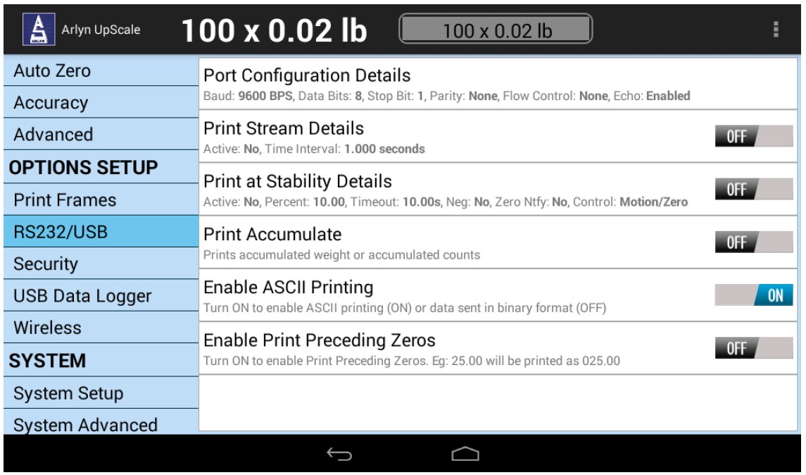
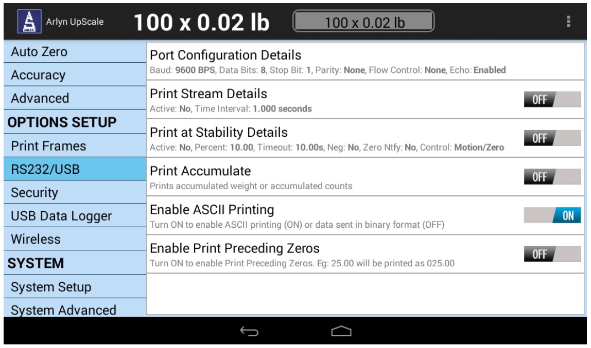
The RS232 Configuration screen can be accessed by going to QUICK MENU->SETTINGS->RS232/USB.
17.1 Configuring the Port
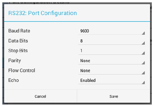
Baud rate and other parameters can be configured through the Port Configuration screen that can be accessed under menu PORT CONFIGURATION DETAILS. The options are shown below.
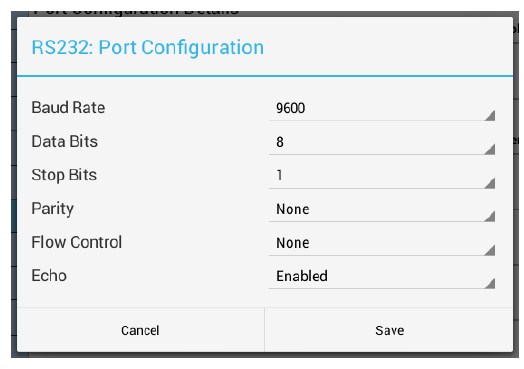
BAUD RATE – Settable to 300 to 921600 bits per second (Default: 9600)
DATA BITS – Seven or Eight (Default: 8)
STOP BITS – One or Two (Default: 1)
PARITY – Even, odd or none (Default: None)
ECHO – When echo is enabled the scale will echo each character the scale receives back to the user (Default: Disabled)
17.2 Test Software for RS232/USB/RS485
We provide some simple software to test out RS232/USB and other RS protocol connectivity mediums. The software can be obtained under the Software Downloads section of our website: https://www.arlynscales.com/software-downloads/
The Arlyn UpScale – Wired application can be used to test out the RS232/USB connection and perform rudimentary datalogging. For more advanced functions for Data Logging and sending weight data to custom applications, we recommend TAL Technologies WinWedge.
To download our Sample PC App test software, download the Arlyn UpScale – Wired application from the link above. Unzip the resulting download and execute the program. Follow the installation instructions as it is similar to other programs. Run the program.
17.2.1 Connection Setup
Press the Setup Tab at the bottom of the program to enter the Setup Screen.
17.2.1.1 RS232/USB SERIAL CONFIGURATION
Make sure that the COM port selected matches the Serial COM port of your computer. The rest of the parameters need to match accordingly with the configuration set in your scale; Baud Rate: 9600, Data Bits: 8, Parity: None, Stop Bit: 1, Flow Control: None
Press APPLY button to have your settings take effect.
17.2.1.2 CONTINUOUS WEIGHT READING
The weight can be continuously read from the scale using this program. To get this working, put a checkmark on the Weight Reading checkbox and set the Refresh Rate to 1000ms. (Note: Setting anything below 1000ms will render the program unresponsive. It will continue to show weights but the window will stay “frozen” on the desktop).
17.2.2 Main Window
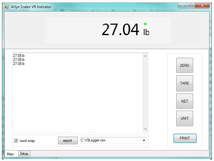
The weight on top of the screen will continuously change if Continuous Weight Reading has been turned on.
Press the PRINT button to get the scale date from the scale. Try the other buttons (ZERO, TARE, NET and UNIT) to see their effect on the scale.
Put a checkmark on the Word Wrap checkbox to have the Print Frames wrap to the second line.
Press the EXPORT button to save all the weights printed on the screen to a .CSV file.
17.3 Test Using Terminal
You can also test the scale communication using a Serial Terminal. To do this, first you will need to download a suitable terminal (if you don’t have one). We recommend RealTerm (https://sourceforge.net/projects/realterm/files/)
Direct Link to File: https://sourceforge.net/projects/realterm/files/latest/download?source=files
In RealTerm (or your favorite terminal), setup the connection using the COM port of your Serial Communication.
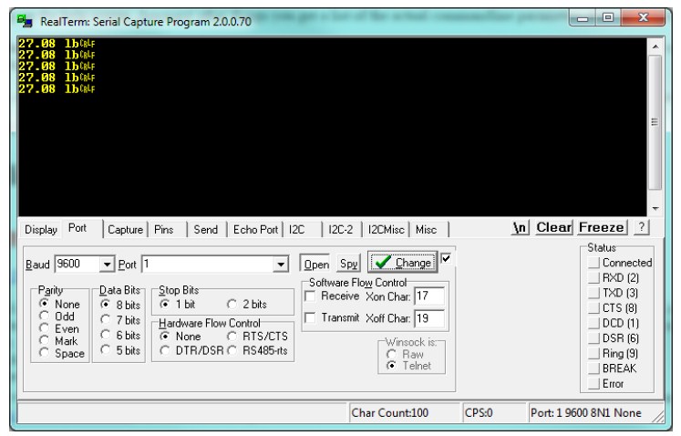
Make sure the Port designation on the bottom right of the screen shows the correct connection parameters. Then press the PRINT button on the scale to start sending data on to the terminal.
Alternatively, you can also send Print Command to the scale to retrieve weight. Use the Send Tab to do this:
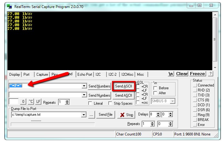
Press the Send ASCII button to send the command to the scale.
If everything works out as specified, the scale is working properly.
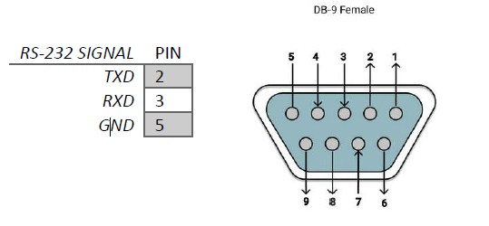
17.4 RS232 D-SUB 9-Pin Connector
17.5 Additional Functions
In order to provide versatile functionality and meeting the needs of our customers, many functions are currently under the pipeline to be added at a future date. Some of these functions are:
17.5.1 Print Stream Mode
Print stream mode will continuously print the currently active print frame at fixed time intervals. Stream mode can be configured using PRINT STREAM DETAILS. The menu selection ACTIVE will enable or disable Print Stream Mode, and TIME INTERVAL (S) will be the number of seconds between the beginnings of each print frame. Avoid using time values of less than .2 seconds as it may slow down or lock up the scale.
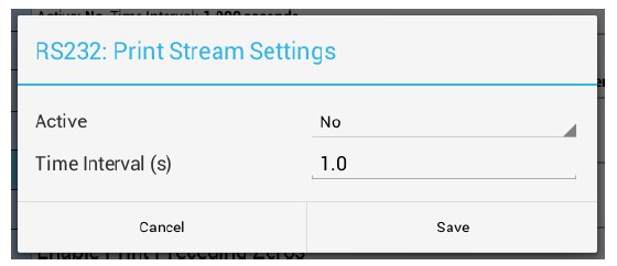
When stream mode is enabled, use the print button or the external ~*P*~ command to start or stop the printing process. You can easily toggle Print Stream by using the ON/OFF button located at the Option Selection.
17.5.2 Printing at Stability Using Motion Detection and Stability Control
All Arlyn digital indicators have the capability of detecting motion and/or stabilizing the weight and using it to control printed outputs. This can be useful in many applications. For example, if you wanted to print labels for several items, you could simply place each item on the platform, and when the scale gets a stable reading it will print the label automatically. The Motion Detect, Stability and printing at stability are fully configurable through their respective setup screens.
The Motion Detect indicator looks like an ‘M’ and it is located just to the right of the Zero Indicator / Bar Graph located on the bottom of the display. It is crossed out if there is no motion, and it is uncrossed if there is motion.
The Stability Control indicator looks like a circle and it is also located just to the right of the Zero indicator/Bar Graph located on the bottom of the display. The circle is unfilled when the weight is not stable and filled when the weight is stable.
Print at Stability configuration allows the user to choose what control they want to use to print. The user can choose Motion Detect only, Stability control only, or both Motion Detect and Stability control. Take a look at the Instructions Manual to see how the Motion Detect and Stability Control can be set.
Sending a PRINT command or pressing the PRINT button on the front panel will send a PRINT request to the scale, and the scale will only print if the motion and stability conditions are met.
17.5.3 Print at Stability Setup Screen
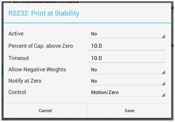
There are five settings that control this function:
17.5.3.1 ACTIVE
This will activate or deactivate this function.
17.5.3.2 PERCENT OF CAPACITY ABOVE ZERO
This is the percent of full-scale capacity, which, if the scale reading falls below, will not automatically print. For example, a 100lb full capacity scale set to 1% will not automatically print when there is less than 1lb on the platform. In most applications there is no purpose to generating a print after removing weight from the platform. This percent can be set to two decimal places.
17.5.3.3 TIMEOUT
This is the time set by the user to timeout retrieval of the value after a certain period of time. By default, this value is 0, which means that the scale is never going to timeout to print a weight value. It will continue to look for a stable point to retrieve a weight value for printing. If the number is set other than 0, then this is the period that the scale will try to print a weight value, and if it fails, it will print “TIMEOUT” in ASCII on the terminal.
17.5.3.4 ALLOW NEGATIVE WEIGHTS
By setting this to “YES”, the automated print will work on both sides of zero. When set to “NO” it will only work with positive weights. The user must take into consideration here that if this parameter is set to “NO”, then when the scale is reading zero, the output may be erratic even though the scale is stable. This is because the value 0 in the scale is not a true stable zero. The zero here may be a long decimal that goes beyond the resolution. In this case, the value maybe negative and therefore, impeding the printing process. It is recommended to set this to “YES” if the zero value is important.
17.5.3.5 NOTIFY AT ZERO
If this option is set to “YES”, then each time the scale is zeroed or a zero command is sent through one of the communication ports, the indicator will wait for the scale to stabilize and detect if there is no motion. Once these conditions are detected, the word “ZERO” appears on the output terminal in ASCII.
CONTROL: This option can be switched between Motion, Stability, Motion and Stability based on your preferences. This determines how you want the Print at Stability to operate, whether based on Motion Detect, Stability Control or both. It is important that when you choose these options, these features need to be activated within the system to operate properly.
17.5.4 Print Stream Mode with Print at Stability
Print Stream and Print at Stability can work together. If you want the scale to print weights constantly, then activate both of these features together and they will work in tandem with each other.
18 USB COMMUNICATIONS (VIRTUAL COM PORT)
The USB communication framework technically sits on the RS232 framework described in the RS232 Section above. This is why there is no dedicated USB Communication Options screen. The RS232 framework controls all operations concerning USB communication. Even in scales with both RS232 and USB communication, the RS232 framework will control both communication mediums.
The RS232/USB Configuration screen can be accessed by going to QUICK MENU->SETTINGS->RS232/USB.
18.1 Configuring the Port
Since the USB communication works on the RS232 backbone, and since the USB connection enumerates as a Virtual COM Port on your computer, it has the same parametric configuration as an RS232 connection. Therefore, baud rate and other parameters can be configured through the Port Configuration screen that can be accessed under menu PORT CONFIGURATION DETAILS. The options are shown below.
BAUD RATE – Settable to 300 to 921600 bits per second (Default: 9600)
DATA BITS – Seven or Eight (Default: 8)
STOP BITS – One or Two (Default: 1)
PARITY – Even, odd or none (Default: None)
ECHO – When echo is enabled the scale will echo each character the scale receives back to the user (Default: Disabled)
18.2 USB Driver Installation
For Windows 7 and later, there is no need for a manual driver installation. As soon as the USB is plugged in, Windows will automatically install drivers. In those unusual cases that Windows doesn’t do this automatically, a CD is provided for Driver Installations. For other Operating Systems such as Linux/Unix, follow the OS’s instructions in installing the driver from the provided CD.
In Windows 7 and later, once the driver installation is complete, you will need to note down the Serial COM Port Number the scale is assigned to. This can be found in Device Manager in the Control Panel.
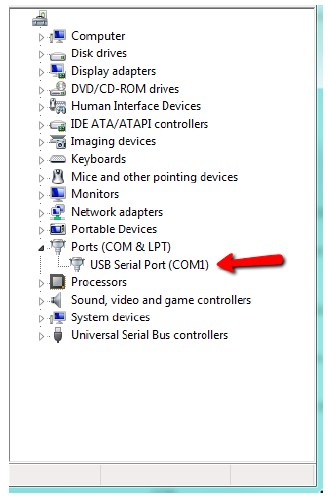
In the image above, our scale has been assigned to COM 1.
18.3 Test Software for USB
After a successful installation, test out the connection using our provided Sample PC App. This step is not necessary if you have tested it out through other means such as a terminal (see Test Using Terminal section below). Install the PC App provided at the Software Downloads page in https://www.arlynscales.com/software-downloads/
The Arlyn UpScale – Wired application can be used to test out the RS232/USB connection and perform rudimentary datalogging. For more advanced functions for Data Logging and sending weight data to custom applications, we recommend TAL Technologies WinWedge -> http://www.taltech.com/winwedge.
See Test Software For RS232/USB heading in the RS232 Communication section for further details on how to use this software. The connection setup should be the same since the USB connection enumerates as a Serial COM port after successful driver installation.
18.4 Test Using Terminal
You can also test the scale communication using a Serial Terminal. To do this, first you will need to download a suitable terminal (if you don’t have one). We recommend RealTerm (https://sourceforge.net/projects/realterm/files/)
For further information on using the Terminal for USB Communication test, check the Test Using Terminal heading in the RS232 Communication section.
18.5 Additional Functions
Other functions such as Print Stream and Print Stability are also available under the USB communication. Please refer to the Additional Functions in RS232 Communication section for further details.
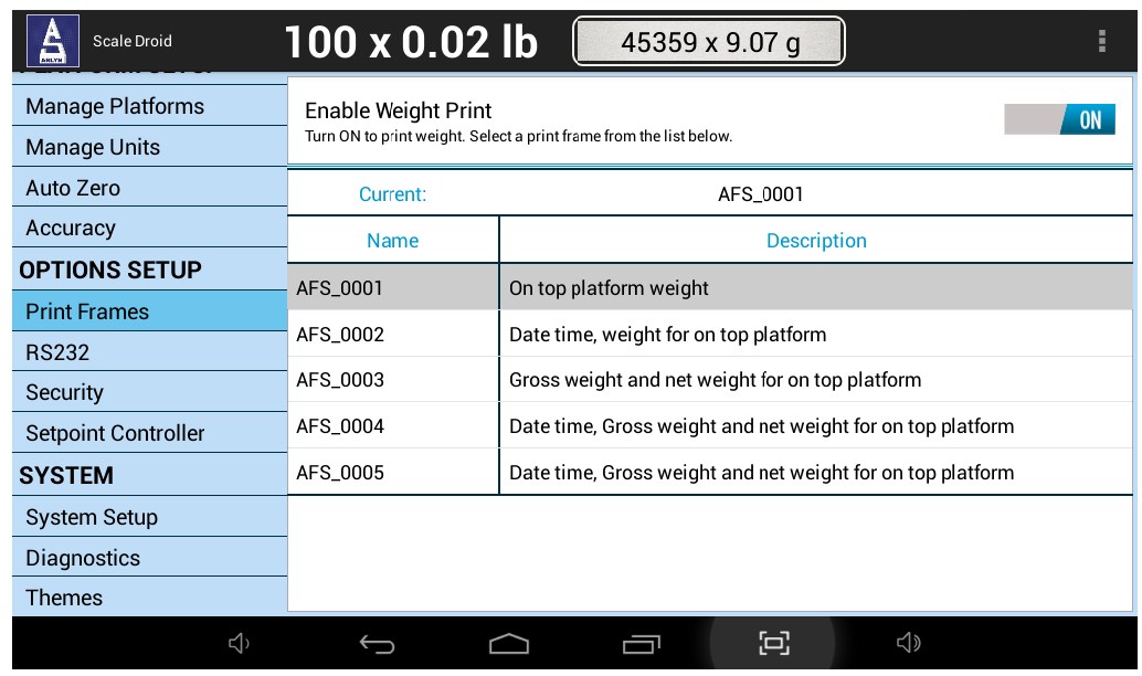
19 PRINT FRAMES (ONLY W/RS232, USB, ETHERNET, WIFI, RS485 or BLUETOOTH)
Print Frames can be considered as templates which the scale uses to format weight printouts before sending them out to the connected medium (PC, PLC, etc.) The current selected Print Frame tells the scale to print out Weight and Unit only.
You can select a different Print Frame to suit your needs. These are predefined Frame Scripts that allows you to print more information when the user presses the PRINT button. A customized Print Frame can be created for your needs if desired.
This topic will be further expanded upon in later versions of this manual.
19.1 Print Format
By default, the scale is configured to print out a Weight with Unit. For example, if the weight is reading 50.00lb, pressing the PRINT key will send the weight in ASCII. This is selected as AFS_0001 from the above selected frames.
Example:
50.00 lb
Generic:
< WEIGHT > < UNIT >
Take note of the space character between weight and unit.
This is called the Print Frame. Different frame types can be selected to meet customer needs.
*Multiple Platform Special Note*
For Multiple Platform configuration, the default Print Frame outputs the total sum of all platforms, as well as weights on individual platform. This Print Frame is named AFS_1002 (not shown in the figure above). All the outputs reflect directly what is currently showing on screen. Here is an example of an output with two platforms.
Example:
08/09/2016 04:24:36, 35.2 lb, 25.0 lb, 10.2 lb, NA, NA
Generic:
< TIME AND DATE >, < TOTAL WEIGHT > < TOTAL UNIT >, < P1 WEIGHT > < P1 UNIT >, < P2 WEIGHT > < P2 UNIT >, < P3 WEIGHT > < P3 UNIT >, < P4 WEIGHT > < P4 UNIT >
Each item in the frame is delimited with a comma character and space character. The example shows “NA” notations in the last two slots. This is to show that those platforms are not available in this scale.
20 PRINTER (Bluetooth/USB/RS232)
Arlyn UpScales can also come with an optional Point Of Sale Thermal Printer. Arlyn Scales provides supported printers that are guaranteed to work with our scales. There is no need for setup or configuration. These printers are connected right out of the box.
Arlyn Scales provides printers with a range of connectivity options:
- Bluetooth
- USB
- RS232 (Special Case for Impact Printers)
20.1 Initial Preparation
The printer should come loaded with paper roll from the factory so you can get quickly started. When the roll of paper is finished, consult the Printer Setup addendum that came in the package to reload the roll paper.
20.1.1 USB Printers
When the scale is shipped from factory, it will already be configured for USB printing (if the option has been requested and enabled). The scale indicator will have a USB connector hanging on the underside clearly labeled as “Optional Interface” or simply as “Printer”. Follow the proceeding steps to setup your Printer.
-
- Make sure all the items are initially powered off. This includes the scale and printer.
- Power up the Printer first. Use the power cable provided with the printer to power up the Printer.
- There is a power switch under the printer. Switch the power to ON to turn the printer on.
- Connect the USB cable under the printer, or on the side of the printer.
- Now that the printer is on, power up the scale by plugging the power micro-USB jack into the micro-USB slot under the indicator.
- Wait for the indicator to power up.
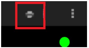
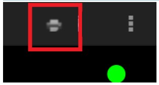
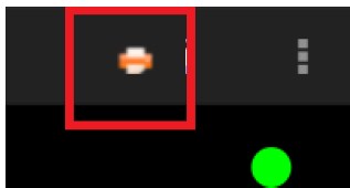
- When you see the main weight screen (with green weight showing on screen), there should be a grayed out “Printer” indicator at the top right of the screen.
-
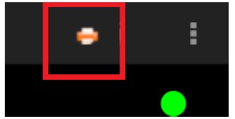
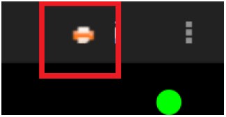
- Plug in the Printer USB plug into the “Printer”/”Optional Interface” USB slot of the indicator. After a few seconds, the “Printer” icon will turn orange.
- You can press the PRINT button on the screen to test print some weights.
20.1.1.1 FORCE PRINTER USB CONNECTION
If the scale does not establish connection with the USB Printer as stated above in a timely manner, you can force the connection by using the Quick Menu selection “Reconnect USB Devices”.
20.1.2 Bluetooth Printers
For easy setup, proceed with the following steps to connect your printer to the scale.
-
- Make sure all the items are initially powered off. This includes the scale and printer.
- Power up the Printer first. Use the power cable provided with the printer to power up the Printer.
- There is a power switch under the printer. Switch the power to ON to turn the printer on.
- Now that the printer is on, power up the scale by plugging the power micro-USB jack into the micro-USB slot under the indicator.
- Wait for the indicator to power up.
- When you see the main weight screen (with green weight showing on screen), there should be a grayed out “Printer” indicator at the top right of the screen.
-
- After about 15-20 seconds, this “Printer” icon will turn orange. This means that the Printer is now connected. You can press the PRINT button on the screen to test print some weights.
20.1.2.1 FORCE PRINTER BLUETOOTH CONNECTION
If the scale does not establish connection with the Bluetooth Printer as stated above in a timely manner, you can force the connection by using the Quick Menu selection “Connect Bluetooth Printer”.
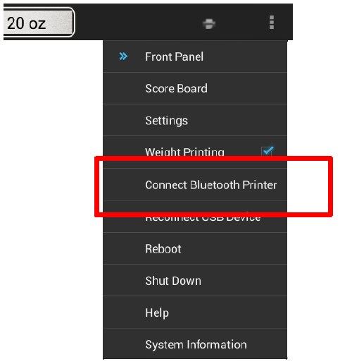
You will be presented with a dialog box showing which Bluetooth Printer you want to connect to.
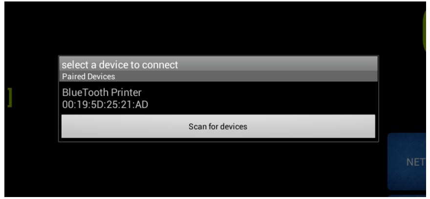
You may see other Bluetooth items appear on this screen. Even though this screenshot shows “Bluetooth Printer” on it, this is not always the case. Sometimes you will see the words “null” on the Bluetooth address. You must check the printer and note the Bluetooth address on it. You must then match the Bluetooth address on the Printer to the address on this dialog box.
Once you have verified the address, touch the address and the scale will proceed to connect to that address. If the connection is successful, you will see the “Printer” indicator on the top right of the screen turn orange.
You can now press the PRINT button to test the scale.
20.1.3 RS232/Impact Printers (Special Case)
For RS232 Printers, the “Printer Status” indicator as seen in the printer types above is not shown. However, the procedure to setup the printer is almost similar:
- Make sure all the items are initially powered off. This includes the scale and printer.
- Power up the scale by plugging the power micro-USB jack into the micro-USB slot under the indicator.
- Wait for the indicator to power up.
- Connect the RS232 cable from the indicator into the Printer Serial connection socket located under the printer. (The printer usually has a 25-pin serial connection. A 9-pin adapter is usually included for this case.)
- Power up the Printer. Use the power cable provided with the printer to power up the Printer.
- There is a power switch on the side of the printer. Switch the power to ON to turn the printer on.
- Once the status LED on the printer is green (paper loaded, etc.), press the PRINT button the indicator.
- Check to see if the printer has printed characters on the paper. Press the FEED button on the printer to move the paper roll outwards.
20.2 Print Frames
If the default Print Frame being printed on the Thermal Printer is not acceptable, we offer five more variations of the print frames. Check out Print Frames to learn about this feature. If the Print Frames offered are still not acceptable, Arlyn Scales can design a Print Frame for you based on your requirements at a nominal fee.
20.3 Printer Setup (Bluetooth & USB Type only)
The Printer Setup screen allows the user to select preferences based on your requirements. The screen is only relevant for Bluetooth and USB Type Thermal Printers. For RS232 printers, the RS232 Communication screen needs to be used. The Printer Setup screen can be accessed by the following method: QUICK MENU->SETTINGS->OPTIONS SETUP->PRINTER
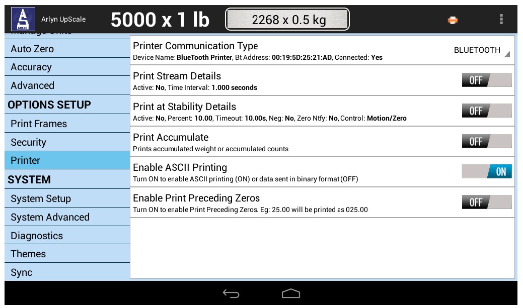
In the Printer Setup screen, you can check out the information about your connected printer such as type of connection (i.e. Bluetooth, USB, TCP/IP, etc.). You can also check the relevant information about your connected printer.
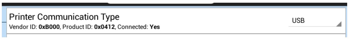
For USB printers, the first selection will look like this:
21 USB DATA LOGGING
The Arlyn UpScale also comes equipped with available USB Flash Drive Data Logging. Data Logging can either be of “Trigger” method or “Periodic” method. Both of these methods are described below.
The Datalogger system can also be configured to send out logs of data through email, either on-demand or periodically. For this capability, the scale must be equipped with Wi-Fi or Ethernet option (sold separately).
With the purchase of the Optional Data Logging, the scale will also come included with a 4GB USB Flash Drive. The USB Stick should not be plugged in during normal operation. It should only be plugged in when Data needs to be exported. Plugging in the USB stick unnecessarily may cause the scale to malfunction. Weights are logged in internal storage. Once you have completed your day, you can choose to export all the data that has been logged into the Flash Drive. At that moment, you will need to plug in the provided Flash Drive to save your data.
If the provided Flash Drive is lost, you can always replace it with your own Flash Drive in any format (preferably FAT or FAT32) to log your data.
The data is exported to a .CSV file (comma separated values), which can be opened using any spreadsheet software such as Microsoft Excel®.
WARNING: DO NOT HAVE THE USB PLUGGED IN DURING NORMAL OPERATION AND WHEN REBOOTING THE SCALE. THE SCALE WILL NOT FUNCTION.
21.1 Basic Operation
There are two modes of operation for using the USB Data Logger:
• Triggered – The weight entry is logged when the user presses a button<
• Periodic – The weight entry is logged at regular time intervals selected by the user.
These modes can be switched in the Data Logger Settings screen.
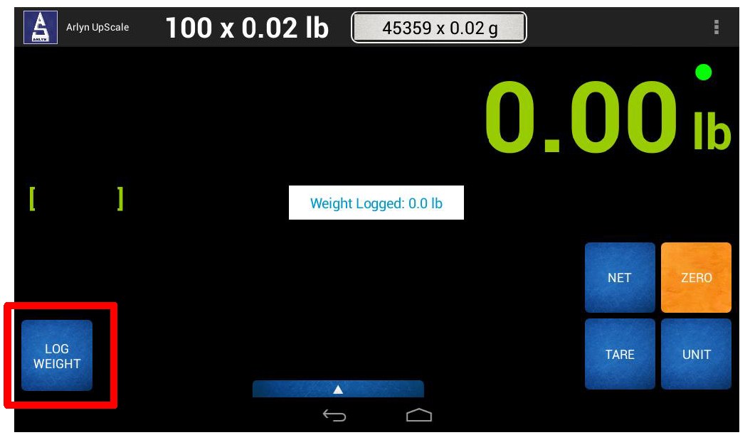
21.1.1 Triggered Mode
In Triggered Mode, the weight will only be logged if you touch the “Log Weight” button. The instantaneous weight shown on the screen at that time will then be logged in the internal table. A message “Weight Logged” will also appear on screen to confirm that the weight has been successfully recorded. An error message will appear in case there was a problem logging the weight.
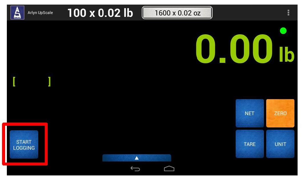
21.1.2 Periodic Mode
In Periodic Mode, the weight will automatically be logged continuously at fixed intervals. These time intervals can be set in the Data Logger Settings screen.
To start the Logging process, touch the “Start Logging” button.
21.2 USB Data Logger Setup
The USB Data Logger Setup screen allows you to setup the behavior of the Data Logging framework.
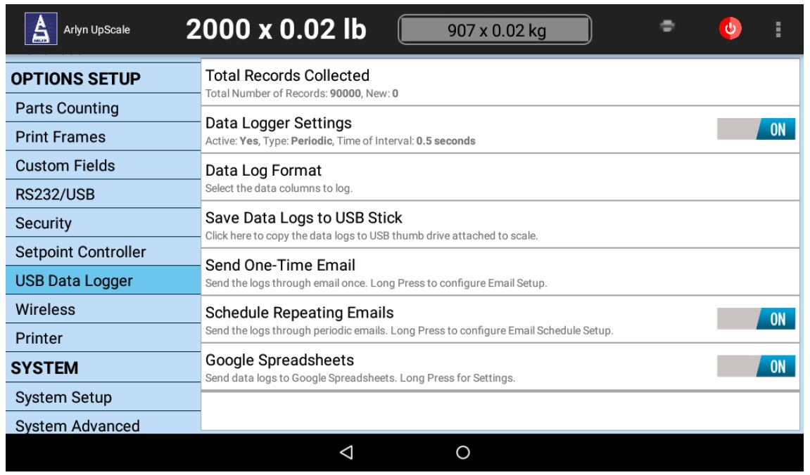
The last two options “Send Via Email” And “Scheduled Email” appear only if the scale is equipped with Wi-Fi or Ethernet option (purchased as additional add-ons).
21.2.1 Total Records Collected
This section shows the number of records that have been collected so far and New Records (that have not been emailed or exported out).
21.2.2 Data Logger Settings
In the Data Logger Settings, you can set how you want the Data Logger to record weights.
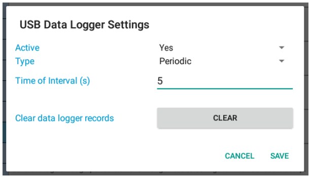
Active – Enable Data Logging feature.
Type – Set the Data Logger mode type to be either Triggered or Periodic. If you set it to Periodic, then the Time Interval field is enabled. You can enter the interval in seconds to set the frequency of logging weights to the internal table.
Time Interval (s) – Set the number of seconds between each logging entry.
Clear Data Logger Records – Press this button to delete ALL data records in the scale memory. Please note that this function is irreversible.
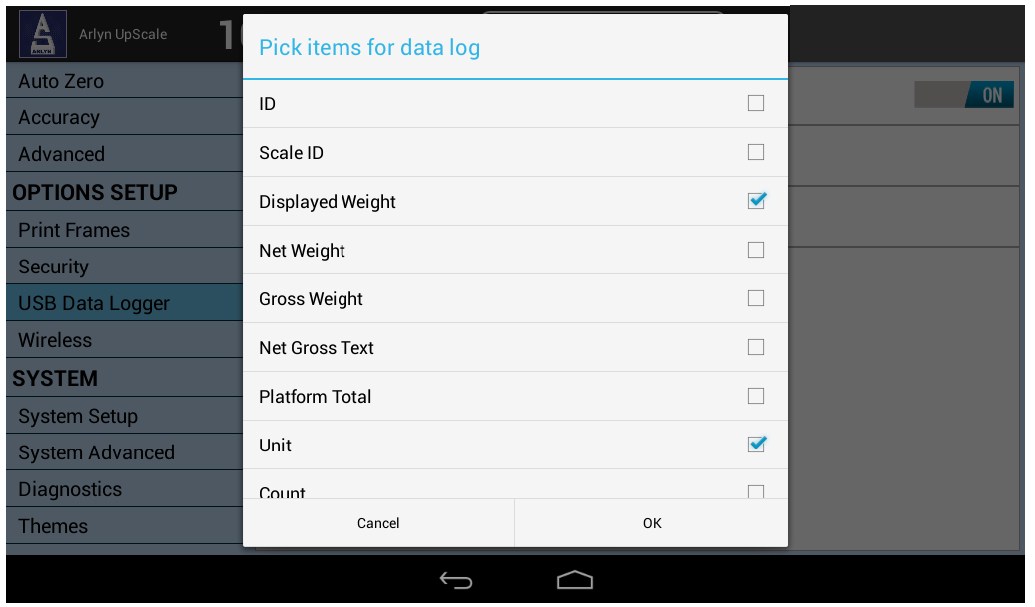
21.2.3 Data Log Format
The Data Log Format setting allows you to set which type of data you want to log. The Weight, Unit and Timestamp have been set by default. You can choose other types of data such as Scale Description, Net or Gross weights, Net or Gross indicators, etc.
21.2.4 Save Data Logs to USB Stick
Once you have completed logging all your data for the day, you can now export this data to the USB Flash Drive. Before proceeding with this step, follow the proceeding steps to begin your export.
a) Plug the USB Flash drive into the provided port.
b) Wait for the USB LED light (if any) to stop blinking.
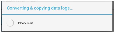
c) Press the “Save Data Logs to USB Stick” option and wait for the process to finish.
d) Once the process is finished, a dialog will appear asking if you want to delete the current data in the internal scale log table.
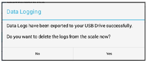
If you select “No”, then the data will remain in the scale. But, if you attempt to export data next time, all the previously exported data in the table will be exported again. At that time, this prompt will appear again asking if you want to delete the logs from the internal scale log table.
If you select “Yes”, then all the data in the internal scale log table will be deleted. Obviously, this is done after saving the data in the USB Flash Drive.
NOTE: After the data is exported to USB, the USB will need some additional time to record data on to the files. Please wait for the “busy” indicator on the USB to stop blinking (if equipped). If a “busy” indicator is not on your USB stick, then wait for about 30 seconds or so for the data to be written. If you pull the USB stick too fast, then you will notice that no new data has been written.
e) Some notes regarding keeping old data logs in the internal table:
a. It is recommended to clear out the internal log tables every time you export data out to the USB Flash drive. You can maintain backups of the data in your own PC/Server.
b. If you do not clear the internal data log table, the next time you chose to save data, it will also save the old data as well as the new data.
c. Keeping old records in the internal data log table will cause the scale to take longer time to save – sometimes taking more than 10 minutes.
If there are more than 500,000 records stored in the internal database, the scale will export the records in batches of 500k. So you might end up with multiple CSV files with 500k records in them. To avoid this, make sure to clear out old records frequently.
The exported data is stored in .CSV format (Comma Separated Values). This file type can be opened by many different programs including Microsoft Excel®. You can sort, plot and analyze the data conveniently in your PC.
WARNING: DO NOT HAVE THE USB PLUGGED IN DURING NORMAL OPERATION AND WHEN REBOOTING THE SCALE. THE SCALE WILL NOT FUNCTION.
21.3 Special Features
The Data Logging option, in conjunction with Wi-Fi or Ethernet, can provide additional capabilities in the Arlyn UpScale indicator. The indicator can be used to:
– Send Data Logs via Email.
– Import/Export Database Definitions.
– Data Log using Google Spreadsheets.
For further information on this and other Special Features, see the Premium Features section.
22 SETPOINT CONTROLLER
The setpoint controller gives your scale the capability to output a signal to external equipment when certain conditions are met. This is particularly useful in filling operations, either to sound alarms or to control filling machinery.
You can even set the setpoint controller to print to a digital port (RS232, USB, Ethernet, Wi-Fi, etc.) or if your scale is equipped with Ethernet or Wi-Fi, the setpoint controller can be configured to send an email out to your inbox when a target weight has reached.
Setpoint definitions can be created, edited and deleted. Each has a text description, controlling parameters and a multi-line formula associated with it. In operation, if the displayed weight satisfies the formula, you may direct any of the outputs to switch on or off. You can create as many setpoint definitions as you like within limits of free memory
Setpoint definitions can be activated or deactivated, and up to four setpoint definitions can be activated at one time. When multiple setpoints are activated, each setpoint formula is evaluated in the order it was defined. If more than one setpoint shares the same output, then it is possible for one to overwrite the other.
With a little finesse in creating formulas, simple setpoints, filling control cycles, over and under check weighing and many other functions are possible.
22.1 Output Specifications and Notes
The setpoint controller has eight separate outputs. Each output is an open collector capable of sourcing 4.5ma or sink 10ma of current. Care must be taken not to exceed these values. This is sufficient to drive LEDs or sound buzzers. If higher output currents are needed then external relays need to be installed. We normally provide 117-240VAC, 10A Optically Isolated Relays and 5-60VDC, 3A Solid State Relays. Mechanical relays should be avoided. Optical relays have some important advantages over mechanical relays; the actuation current for optical relays is usually less than 10ma but mechanical relay coils require currents often exceeding the limit. Optical relays have no mechanical switches to wear out and more importantly they isolate the scale from the load, thus protecting it from voltage spikes. If excessive noise is coupled back to the scale it could lock up or damage its microprocessor or memory.
It should be noted that when you command an “OFF” CONDITION, the output will be grounded. In most open collector (switched ground) wiring schemes this will actuate the external light or relay. To help eliminate this confusion, each setpoint formula has an optional INVERT function to invert the output.
Even though the output is an open collector, it differs from the standard open collector output in that the output will assume a high condition (3.3VDC) when it is switched on without the need for an external pull up resistor, allowing direct connection into any TTL level input.
22.2 Creating Setpoints and Formulas
To access setpoints, go to the QUICK MENU->SETTINGS->SETPOINT CONTROLLER. There you will see a list of all available setpoints or “None Defined” if none exist. The creation, editing and deletion of setpoints are similar to the creation of tares and parts counting samples.
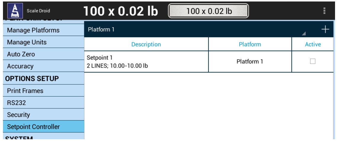
Create a new setpoint definition by pressing the “+” icon on the top right corner of the Screen to open the New Setpoint Definition dialog box.
22.3 The Setpoint Definition Screen
The setpoint definition screen will show the description and controlling parameters for this setpoint definition.
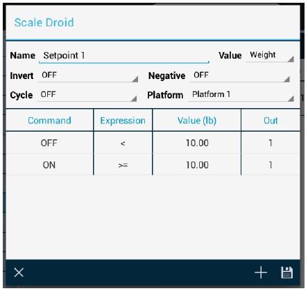
22.3.1 Invert
If it is ON then all outputs related to this setpoint will be inverted. This is useful when using the open collector output for the reasons stated earlier in this section.
22.3.2 Cycle
The cycle option is used to create an operation cycle as described later in this section.
22.3.3 Negative
The Negative option is used to determine if the scale needs to evaluate negative weight values. If NEGATIVE = OFF, then the setpoint controller will not evaluate negative weights, as in it will treat both negative and positive weights the same. For example, if the display shows -10lbs or +10lbs, the setpoint evaluator will evaluate these values as positive values. If Negative=ON, then it will differentiate between the two values.
22.3.4 Platform
*Multiple Platform Special Note*
This option only works when the scale is equipped with multiple platforms. The user can select if the setpoint conforms to a particular platform. If it is the case, then the setpoint will only evaluate weights corresponding to that platform. For single platform scales, the option will just show Platform 1.
22.3.5 Value (Only for Parts Counting Scales)
This option only works when the scale is equipped with Parts Counting. The user is given a choice of whether the setpoint should respond to count value instead of weight value.
To change any of these options simply select the appropriate entry in the corresponding field label.
22.4 Creating and Editing Formulas
The formula is a list of up to 16 lines that are evaluated and acted upon in the order they are entered.
To access the formula list select EDIT in the lower menu and then press ENTER. All of the current formula lines will be displayed or “None Defined” if there aren’t any. Use the icon to add a new command line. Use the Save icon to save the current formula (list of command lines).
Each line consists of four parts. These are Command, Expression, Value and Out.
– Command is an action to take. The only two commands currently available are ON and OFF.
– Expression can be < (less than), <= (less than or equal to), > (greater than) and >= (greater than or equal to).
– Value is the setpoint weight or count value.
– Out is the output channel (1-8) that the Command will work on.
For example, a simple formula to activate the output when a certain weight is exceeded is made up of two lines as shown below:
| Command | Expression | Value | Out | Comment |
| OFF | < | 10.00 | 1 | Start with the light off |
| ON | >= | 10.00 | 1 | Turn on if 10lbs or greater. |
This can be interpreted as:
Line 1: Output #1 is off if weight is less than 5.00lb
Line 2: Output #1 is on if weight is greater than or equal to than 5.00lb
You will notice that every output possibility must be dealt with when creating a formula.
The next example represents a much more complicated definition. The scale would have three lights connected to three outputs and operate in an UNDER / ACCEPT / OVER check weighing scenario.
There will be a
– Red light connected to output #1 to indicate an “under” condition,
– Blue light connected to output #2 for an “accept” condition and,
– Green light connected to output #3 to show an “over” condition.
We can program the Red light to be on whenever the weight is less than 5lb, the Blue light to be on only between 5 and 10lb and the Green light to be on whenever the weight is above 10lb indicating an over condition. In practice, the user would start filling the container until the Blue light comes on.
It is less confusing to make a formula of this nature if you deal with the complete operation of one light at a time. We recommend laying the formula out on paper first and then enter it into the system.
Here it is:
| Command | Expression | Value | Out | Comment |
| ON | > | 0.00 | 1 | Deal with “under” (Red) light first |
| OFF | >= | 5.00 | 1 | |
| OFF | < | 5.00 | 2 | Now the “accept” (Blue) light, to be |
| ON | >= | 5.00 | 2 | on only between 5 and 10lbs |
| OFF | > | 10.00 | 2 | |
| OFF | <= | 10.00 | 3 | Now the “over” (Green) light to be on |
| OFF | > | 10.00 | 3 | Anytime the weight is above 10.00lb |
When this formula is executed, the scale evaluates each line in order. This calculation is done in memory only, and the outputs are not affected until the formula is complete. The entire formula is evaluated on each and every display update, which is programmable through the system menu.
You may wonder why it is necessary to have to use an OFF condition at the beginning. This was done to increase flexibility as there may be many cases where the user wants the light to start in the on state, turn off during a certain weight range and on again when above that range. You have to specify every possible condition for the output when making formulas.
22.5 Cycle Mode
This last example will show an automated filling operation using the cycle option. The goal here would be to have Output #1 connected to a filling valve and the cycle starting with this valve in the off condition.
Operational Steps:
– The user places a box on the scale below the filling apparatus.
– Press the ZERO key to zero out the weight of the box.
– Press the CYCLE key to start filling and have the setpoint controller switch the filling valve off when 5lb is reached.
– The user then removes the box from the scale and the output will remain off until the next cycle is initiated by pressing the CYCLE key.
Start in the setpoint definition screen by setting the Cycle field to “Yes”.
Here is the formula:
| Command | Expression | Value | Out | Comment |
| OFF | < | 5.00 | 1 | Will actually go on as soon as the CYCLE key is pressed. |
| ON | >= | 5.00 | 1 | Switch off at 5lb and end cycle. |
That’s all there is to it. The output will go off at 5lb and remain off until the next cycle.
22.5.1 Notes on Cycling Setpoints
The cycle function is used when it is desirable to “latch” the output to a specific state when a process is complete. Consider the following examples with and without the cycle option. In both cases the setpoint is set to fill a box to 5lb and then shut off.
Cycle Off – The output is on as the box fills and the scale monitors the process. At 5.00lb the output switches off. The user then removes the box from the scale. When he does that, the indicated weight falls below 5.00lb, the filling valve switches back on dumping material all over the platform.
Cycle On – When 5.00lb is reached the output switches off, and remains off until the user initiates the cycle again by pressing the ENTER key.
There are two other points concerning process cycles:
– There may only be one cycling setpoint definition active at any given time. All other activated setpoint definitions will work normally along with it.
– To abort the cycle, press the CYCLE key. The output will then obtain the same state it would have taken if the process had completed normally.
22.5.2 Cycle Remote Button Feature
If it is required that the CYCLE button needs to be activated while you are at a distance from the indicator, the Arlyn UpScale indicator can be equipped with a remote activation feature through a two-wire cable.
Basically, instead of going to the scale each time and pressing the CYCLE button, the indicator can be equipped with a long cable (about 10ft standard) with two wire terminals at the end of it (typically red and white). Touch these two wires together will actuate the CYCLE button. This way, you do not need to be near the scale each time to start the cycle.
22.6 Output Connector and Pin Diagram
In most cases there will be a single cable with a 15 pin subminiature D type female connector added to the scale for interfacing to external equipment.
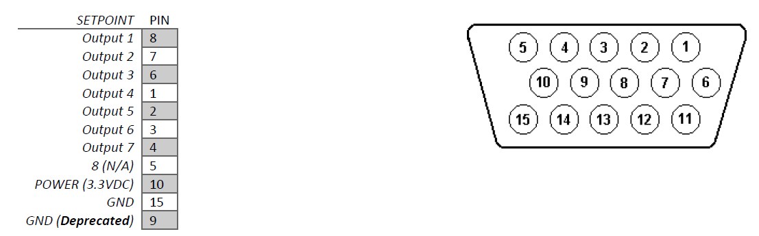
22.7 Special Features (Beta)
Setpoint Print – If your scale is equipped with Printing outputs (such as RS232, USB, Wi-Fi, Ethernet, etc.), then you can use the Setpoint Controller to print out a frame of data at specific target weights.
Setpoint Email – If your scale is equipped with Ethernet of Wi-Fi, then you can also configure the scale’s Setpoint Controller to send an email out to you at specific target weights.
For further information on this and other Special Features, see the Premium Features section.
23 WIRELESS CONNECTIVITY
The Wireless connectivity option is a fully capable, bi-directional communication medium. The connection can be configured to support DHCP or static IP at a specific port number on your network. The printing of a frame can be initiated by pressing the print button, by an external command, upon reaching a setpoint, or continuously when the print stream mode is activated.
The communications port also contains an extensive external command interface allowing key presses, adding and editing memory slots and even scale calibration to be controlled from external equipment.
The Wireless Configuration screen can be accessed by going to QUICK MENU->SETTINGS->WIRELESS.
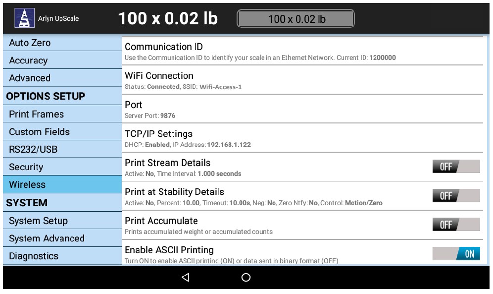
23.1 Automatic Connectivity (DHCP)
Press the Wi-Fi Connection option. This will prompt the scale to scan your nearby Wi-Fi access points. Touch on the one that you want to connect to and you will be presented with the following dialog.
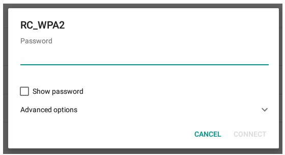
If you want the scale to do a simple connection (DHCP) with your network, just enter the WEP/WPA/WPA2 password of your wireless network and press the connect button. For advanced configuration such as Static IP, proceed to section Static IP Configuration Section.
If the password is entered correctly, then after a about 30 seconds or so, you will see the Status changed to Connected and the SSID you are connected to, show up on the Wi-Fi Connection row.
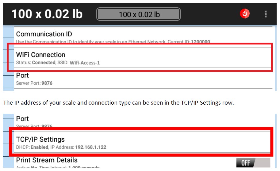
23.2 Setting the Wireless TCP/IP Socket Port
Next, we need to change the Wireless TCP/IP port that will allow you to open a socket connection into the tablet indicator. This part is not necessary, but we recommend you to do it so that you can be familiar with the interface.
By default, the port is 9876. To change this, touch the Port Row and you will see the following dialog come up.
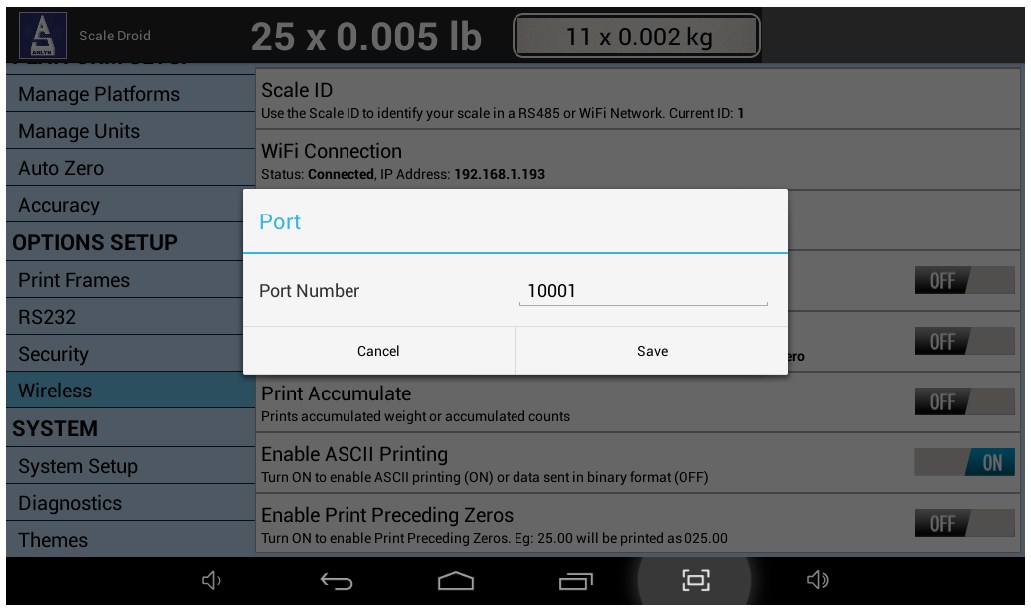
Change the port number to 10001. This will be easy to remember when making your connection. Once you complete this, press SAVE and then press the BACK button to go to the main weight screen.
23.3 Static IP Configuration
Suppose the DHCP configuration is not desirable, you can change to Static configuration. To do this, touch the “Wi-Fi Connection” option on the Wireless Settings page, and you will see this following dialog box.
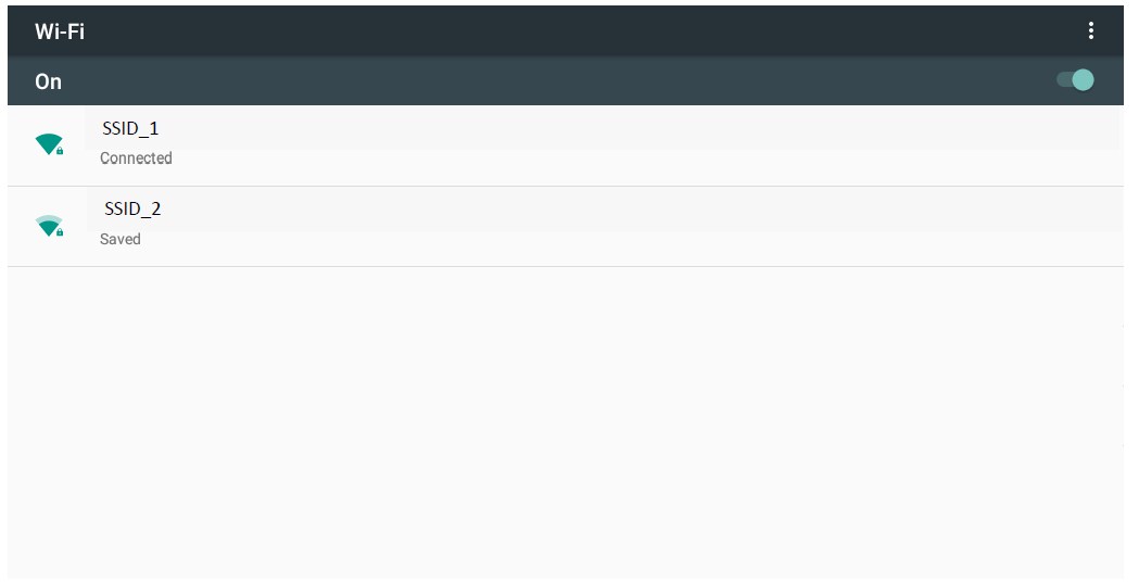
a) Pick the Wi-Fi access point you want to connect to. The following dialog box will appear.
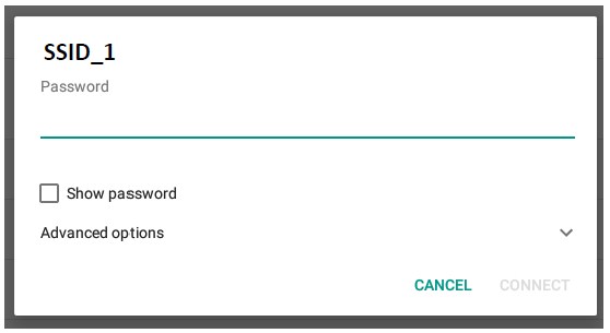
b) Enter the password for the Wi-Fi access point. It is recommended to check the “Show Password” to confirm that the correct password is entered. DO NOT CLICK CONNECT YET!
c) If you do click “Connect” accidentally, (or if you have previously connected to the Wi-Fi SSID), then you must click on the SSID for the access point and press “FORGET’. Then start the process again from the beginning of this section.
d) After entering the password, press on “Advanced Options”.
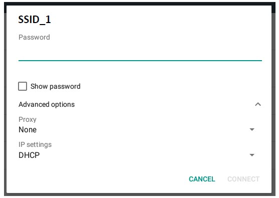
e) Under IP Settings, change the “DHCP” option to “Static IP”. This will drill down to further entry fields as seen below.
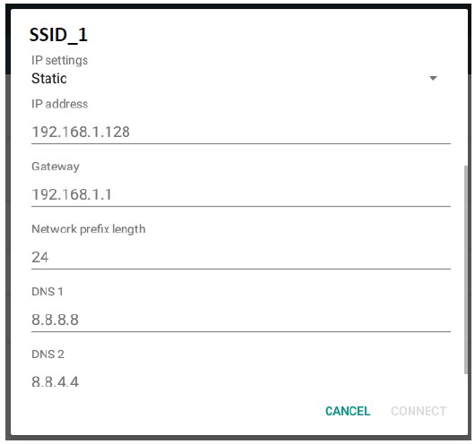
f) You MUST fill out all the fields except for ‘Network Prefix Length’ and ‘DNS 2’. All the other fields are required.
g) Once all the fields are filled, press the ‘CONNECT’ button. If all the fields are filled correctly and the password is correct, then the Wi-Fi Access Point will be connected.
h) Press the BACK-arrow button the bottom black ribbon to return to the Scale Interface.
i) The Static IP address and connectivity will be reflected on the screen.
Proceed to the next section to test out your Wireless TCP/IP communication.
23.4 Test Wireless TCP/IP Communication.
23.4.1 Using ipchat Program
We have provided software written in Java to test the wireless TCP/IP socket connection. This can be accessed under Software Downloads at our website under the following address:
https://www.arlynscales.com/software-downloads/
Unzip the ipchat program on to your computer and run the ipchat.bat file. [Please note, the computer should be in the same subnet as the scale]
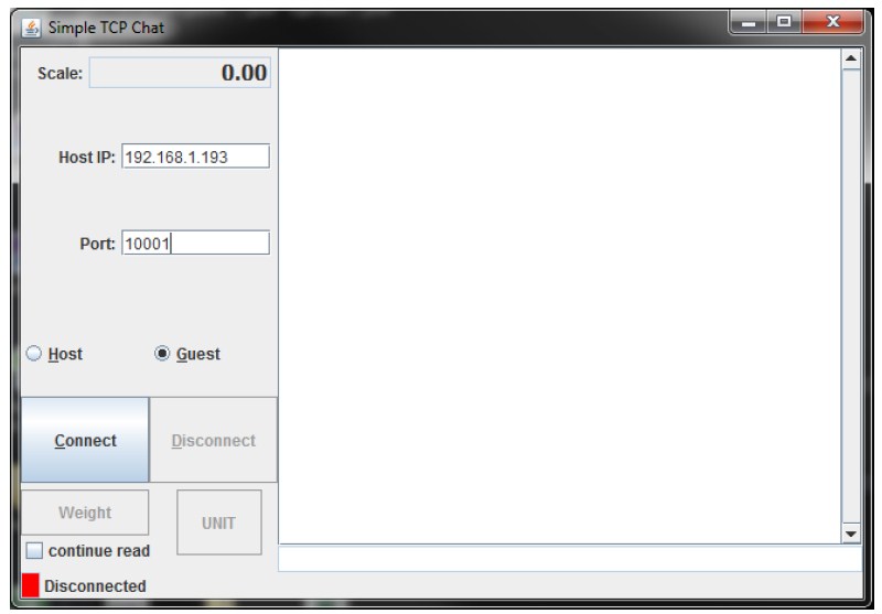
Press the CONNECT button. The scale should be successful connected. Then press the WEIGHT button. You should get a weight back.
23.4.2 TCP/IP Connection Indicator
If there is a successful TCP/IP connection to the scale, the scale will also indicate this connection on the top right corner.
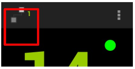
The TCP connection indicator shows the number of concurrent connections the scale has in process. You can have multiple computers connect to the scale at the same time. Each connection will increment this number indicated on the indicator. When the connection drops, the number may not immediately update. It may take some time to drop this number to the actual number of connections the scale is incurring.
23.4.3 Using Terminal
Alternatively, you can use a terminal such as HyperTerminal or RealTerm to communicate with the scale. Just open a socket connection using the scale IP address and port number, and then type the following command:
~*P*~ – To get the weight printed on your terminal.
Other supported commands are:
~*W*~ – Get a JSON string for the weight
~*Z*~ – Zero the scale.
~*U*~ – Switch unit
24 ETHERNET CONNECTIVITY
The Ethernet connectivity option works similarly to the wireless connectivity option with a few differences. This section will detail the setup completely. The Ethernet connectivity option is a fully capable, bi-directional communication medium. The connection can be configured to support DHCP or static IP at a specific port number on your network. The printing of a frame can be initiated by pressing the print button, by an external command, upon reaching a setpoint, or continuously when the print stream mode is activated.
The communications port also contains an extensive external command interface allowing key presses, adding and editing memory slots and even scale calibration to be controlled from external equipment.
The Ethernet Configuration screen can be accessed by going to QUICK MENU->SETTINGS->ETHERNET.
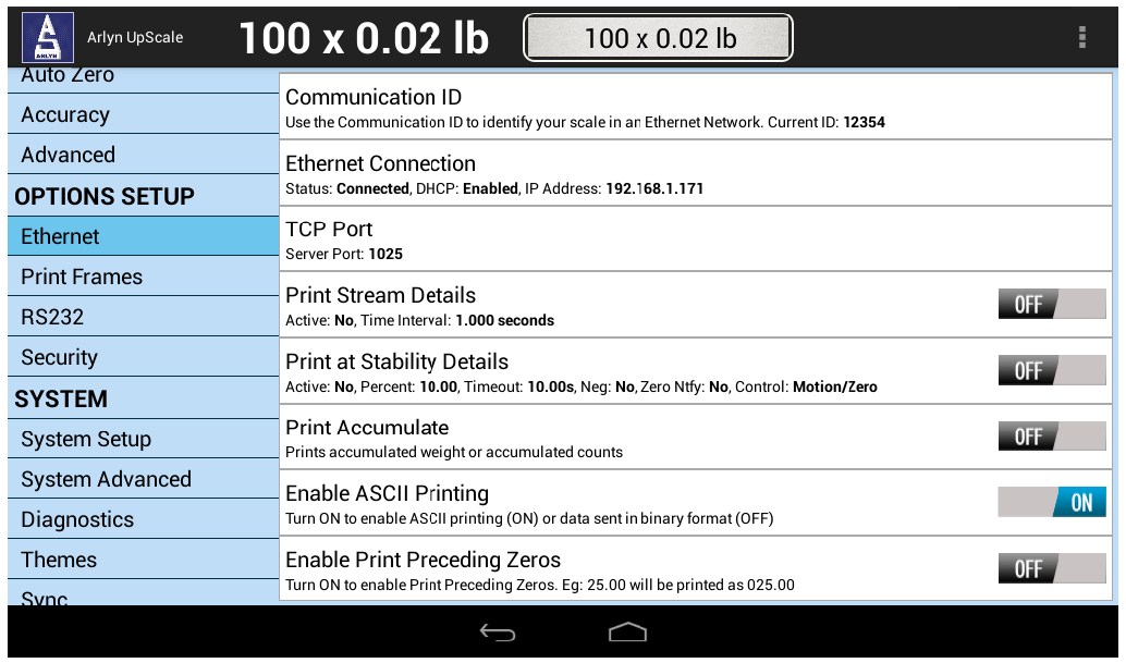
24.1 Ethernet Connection
24.1.1 Connection Information
If your scale has successfully connected to your network, you will see the Ethernet connection message showing you your current connection details.
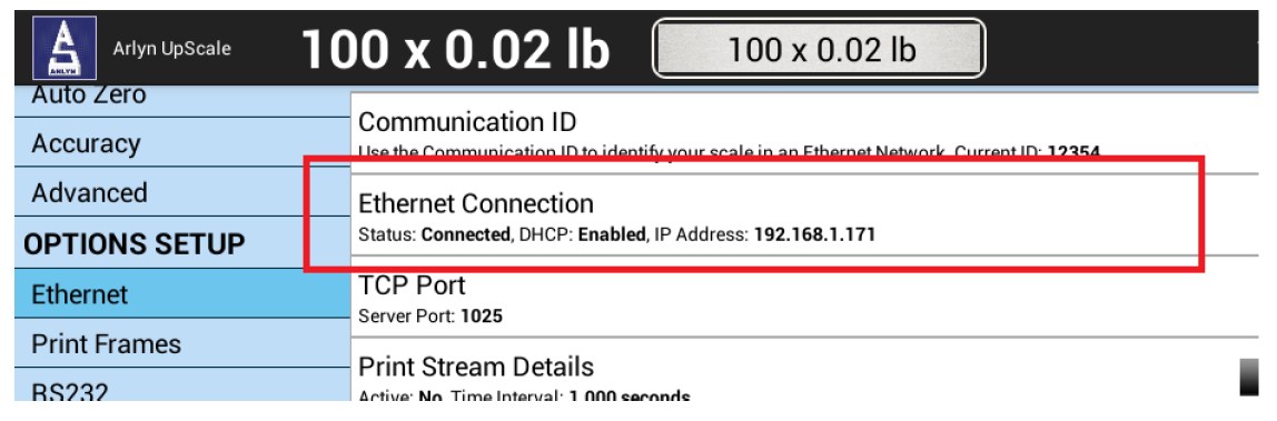
24.1.2 DHCP
By default, the scale ships with DHCP connection settings. This means as soon as you plug an Ethernet cable on to the scale, the scale will try to obtain an IP address from your router through DHCP. For testing purposes, ensure that your server can support DHCP.
24.1.3 Static Configuration
Suppose the DHCP configuration is not desirable, you can change to Static configuration. To do this, touch the Ethernet Connection option on the Ethernet Settings page, and you will see this following dialog box.
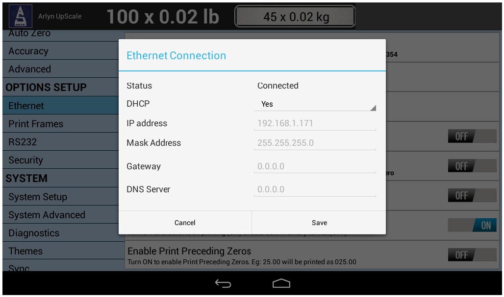
Under the DHCP selection, change to “No”. This will enable the static IP textboxes (similar to the one’s you see in Windows and other operating systems).
Enter the Static IP configuration and press the SAVE button on the dialog box. Your settings will reflect after 10 seconds. You will see the Ethernet Connection info reflecting the new IP address if it is properly set.
24.2 Setting the Ethernet TCP/IP Socket Port
Next, we need to change the Ethernet TCP/IP port that will allow you to open a socket connection into the tablet indicator. This part is not necessary, but we recommend you to do it so that you can be familiar with the interface.
By default, the port is 10001. To change this, touch the Port Row and you will see the following dialog come up.
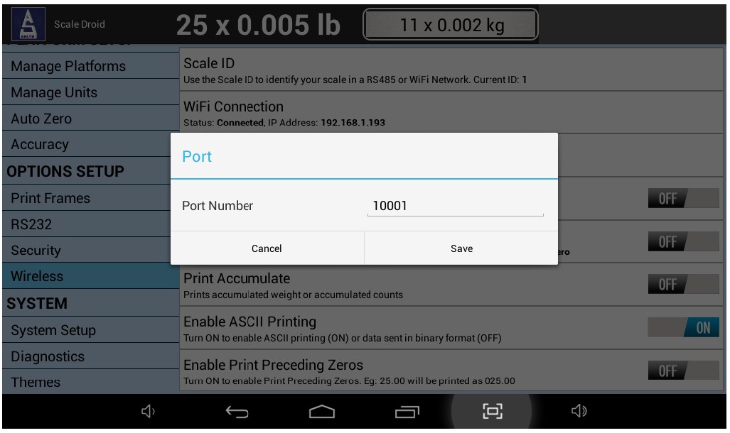
Change the port number to any number you desire. Once you complete this, press SAVE and then press the BACK button to go to the main weight screen.
24.3 Test Ethernet TCP/IP Communication.
24.3.1 Using ipchat Program
We have provided software written in Java to test the Ethernet TCP/IP socket connection. This can be accessed under Software Downloads at our website under the following address:
https://www.arlynscales.com/software-downloads/
Unzip the ipchat program on to your computer and run the ipchat.bat file. [Please note, the computer should be in the same subnet as the scale]
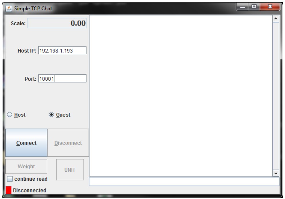
Press the CONNECT button. The scale should be successful connected. Then press the WEIGHT button. You should get a weight back.
24.3.2 TCP/IP Connection Indicator
If there is a successful TCP/IP connection to the scale, the scale will also indicate this connection on the top right corner.
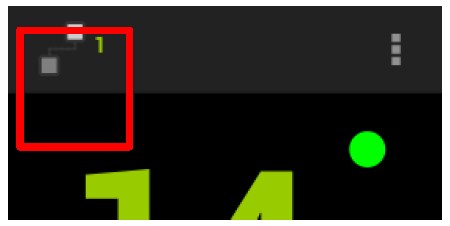
The TCP connection indicator shows the number of concurrent connections the scale has in process. You can have multiple computers connect to the scale at the same time. Each connection will increment this number indicated on the indicator. When the connection drops, the number may not immediately update. It may take some time to drop this number to the actual number of connections the scale is actually maintaining.
24.3.3 Using Terminal
Alternatively, you can use a terminal such as HyperTerminal or RealTerm to communicate with the scale. Just open a socket connection using the scale IP address and port number, and then type the following command:
~*P*~ – To get the weight printed on your terminal.
Other supported commands are:
~*W*~ – Get a JSON string for the weight
~*Z*~ – Zero the scale.
~*U*~ – Switch unit
25 MULTIPLE PLATFORM OPERATION
The scale can optionally be equipped with more than one platform (i.e. up to 3 strain gauge platforms and up to 4 SAW Load cell platforms).
There are slight variations in the way the scale operates for multiple platforms. For these variations, look for the Multiple Platform Special Note in various operations described in this manual.
The Arlyn UpScale indicator can support up to 6 strain gage platforms, and up to 4 Ultra Precession (SAW) platforms within a single display enclosure.
25.1 Front Panel Views
For Multiple Platform scales, there are additional views available on the Front Panel that can be used at your convenience. The Quick Action menu shows the display views available.
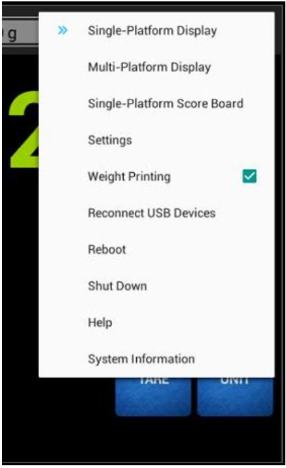 |
Single Platform Display – Shows the weight on an individual platform. Using a simple gesture, you can switch between connected platforms to view individual weight readings. Each platform view has dedicated controls for zero, tare and unit. |
| Multiple Platform Display – Shows the total sum of all the weights from all connected platforms. Additionally, weights from individual platforms are shown in a summary format under the Total. | |
| Single Platform Score Board – Shows the weight on an individual platform in Score Board Format (Large Text). This screen essentially acts the same way as the Single Platform Display but with the convenience of Large Weight Text. |
These display views are explained in detail in the following sections.
25.2 Single Platform Display
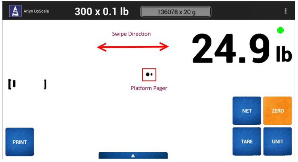
The Single Platform Display shows the weight on one of the connected platforms. The controls shown on the screen correspond only to the platform shown. For example, if the ZERO button is pressed, then the scale will zero out this particular platform.
The Platform Number can be determined by looking at the Platform Pager. The larger sized circle shows the platform selected. In the screenshot above, the Platform Pager has two circles. This means there are two platforms connected. Since the first circle is bigger, then the scale is showing the weight on Platform 1.
Use a “swipe gesture” to show weights on other platforms. Swipe LEFT to show the next platform and swipe RIGHT to show the previous platform.
As soon as the Platform is switched, the controls shown on screen are “internally switched” so they will work directly on the platform shown on the screen.
25.3 Multiple Platform Display
The Multiple Platform Display shows the Total sum of all the weights from all connected platforms. The display also shows the weights on the individual connected platforms in summary format below the Total weight.
A limited number of operations can be done on this screen. To bring up the control buttons, swipe to the left of the screen as shown in the figure below.
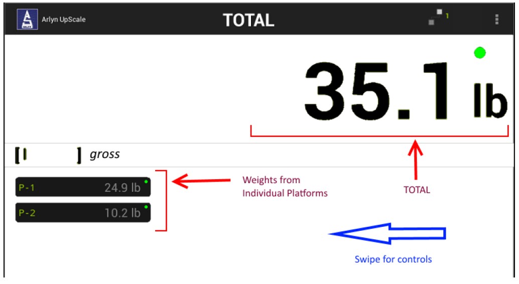
25.3.1 Screen Controls
Swiping to the left of the screen brings out the screen controls.
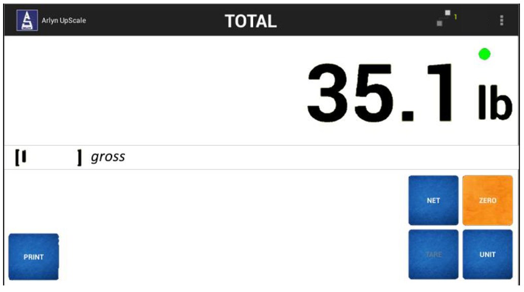
TARE
This button is disabled as this is a platform specific operation.
NET/GROSS
Will toggle the indicator between the net and gross mode. The Net mode will show the net total weight on the platform minus any tared weight from any individual platforms.
UNIT
Pressing this key will show total weight in various units without affecting the display units of individual platforms.
ZERO
The ZERO button on the screen is a special operation that needs to be used carefully. Pressing this button will zero out all the connected platforms. This button should be normally pressed if all the platforms are empty and need to be zero out to adjust any drifts over time.
26 ANALOG OUTPUT
This option is a fully configurable analog output port that can be configured for current loop outputs. The factory has preset the output to 4-20 mA. This range is configurable and it is explained in the second paragraph of this section. The output follows the display and its gain is based on the platform’s programmed overload point. For example, in the case of a 100lb scale whose output is configured as 4-20mA, 0lb = 4mA, 25lb = 8mA, 50lb = 12mA and so on.
The starting and ending currents can be configured by the user. For example, the output’s starting and ending points can be set 4mA to 20mA. Further, there is an option allowing negative displayed numbers to be output for cases where a reading below zero needs to be monitored. As an example, a 100lb scale is setup with its starting current at 10mA and ending current at 20mA, giving the output of -100lb= 0mA, -50lb = 5mA, 0lb = 10mA, 50lb = 15mA and 100lb = 20mA.
The Analog Output can also be configured to output voltage. The output can be configured for a voltage range between 0-5VDC. This configuration can be requested to be done at the time of processing the order. However, this can also be done by the customer. Simply connect a 250-ohm ¼ watt resistor between the output terminals. Set the starting and ending currents to be 0mA and 20mA. Using Ohm’s law (V = I x R), you will get from 0VDC (0mA x 250 ohm = 0V) to 5VDC (20mA x 250 ohm = 5V). Just put a voltmeter across the terminals to get these values.
Using any value of the resistor, the scale can be configured to output a customized range of voltages based on customer requirements. However, the voltage cannot exceed 5VDC. The current output component cannot support a voltage drop larger than this value.
26.1 Analog Output Setup
The Analog Output Settings can be used to set the “Start Current Value”, “End Current Value”, the weight associated with these values as well as toggling “Allow Negative” setting. It is strongly recommended to keep these settings as set by the factory unless there is a special need to change these settings based on your specific requirements.
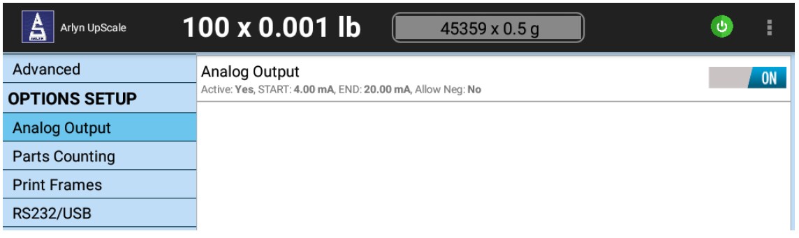
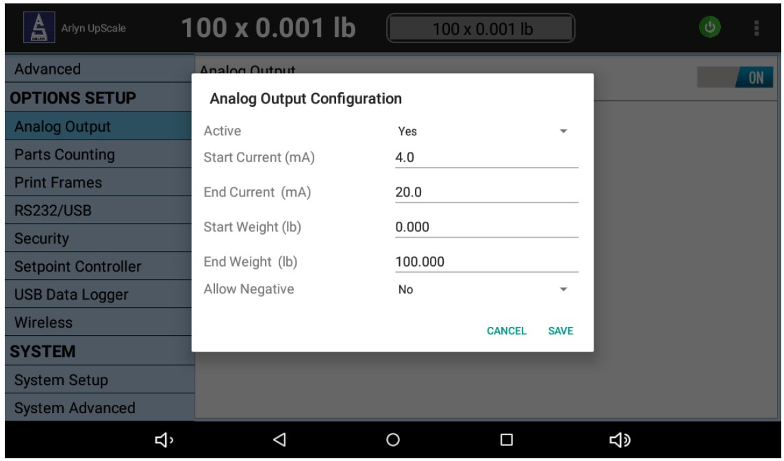
Active – Allow the scale to produce Analog Output signal.
Start Current (mA) – This is the current reading that the scale will output when there is no load on the platform (i.e. 0lb). This weight value can also be changed in “Start Weight” field.
End Current (mA) – This is the current reading that the scale will output when the platform is loaded to its specified capacity. This weight value can also be changed in “End Weight” field.
Start Weight – The weight which is related to Start Current (Default: 0lbs).
End Weight – The weight associated to End Current (Default: The set capacity of the scale)
Allow Negative – Allows negative displayed readings to affect the analog output. If disabled, the output will stop at the programmed starting current when there is a negative number on the display. This should not be confused with a negative current on the output. The lowest possible current is zero.
Press the “SAVE” button to save the current configuration.
26.2 Analog Output Wiring Diagram
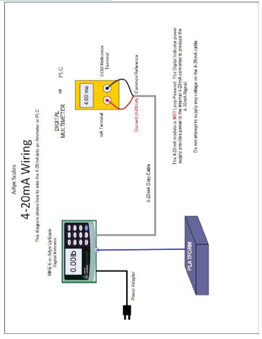
PART III
Beta
Premium Features
27 PREMIUM FEATURES (Beta)
The following features are additional functions that can be additionally configured on some select options. These features are provided “as is” without technical support apart from the base options provided. Some features require multiple options to be enabled to work. Please see terms and disclaimers regarding this and other premium features outlined in the Limited Warranty section.
28 SETPOINTS – PRINT AND EMAIL (w/ Digital Outputs)
Important Note: This feature is provided as a “Premium Feature (Beta)”. Please see terms and disclaimers regarding this and other premium features outlined in the Limited Warranty section.
28.1 Overview
Setpoint Print – If your scale is equipped with Printing outputs (such as RS232, USB, Wi-Fi, Ethernet, etc.), then you can use the Setpoint Controller to print out a frame of data at specific target weights.
Setpoint Email – If your scale is equipped with Ethernet of Wi-Fi, then you can also configure the scale’s Setpoint Controller to send an email out to you at specific target weights.
For example, if you want the scale to print out data when it reads above 50lbs, you can set your commands to not only turn on an output when it reads 50lbs but also PRINT out data to all the outputs available on the scale. Similarly, you can also configure the same setpoint to email you when it reaches 50lbs.
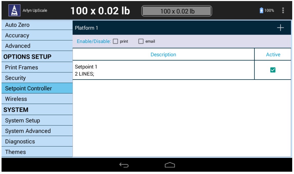
In this screen, the top bar shows “Enable/Disable – ? Print ? Email”.
Setpoint Print – Enable the Setpoint print function. When the PRINT option has been set in any of the setpoint command lines, the scale will print out the current weight on the platform to all connected outputs.
Setpoint Email – Enable the Setpoint email function. When the EMAIL option has been set in any of the setpoint command lines, the scale will email out the current weight on the platform to the email specified on this email field.
When enabling the “Setpoint Email” option, specify the email to which the scale will email the current weight on the platform.
28.2 Print and Email Trigger Points
It is important to note that the email and the print triggers are tied to the state of the Setpoint Output – (the LED on the Front Panel screen). If the LED turns ON and the command line satisfying this condition is configured for email, then the scale will email the data at the point of the LED turning on.
Similarly, if the LED turns OFF and the command line satisfying this condition is configured for email, then the scale will email the weight data at the point of LED shutting off.
These cases also apply to the Setpoint Print functionality.
28.3 Setpoint Command Line Configuration for Email/Print
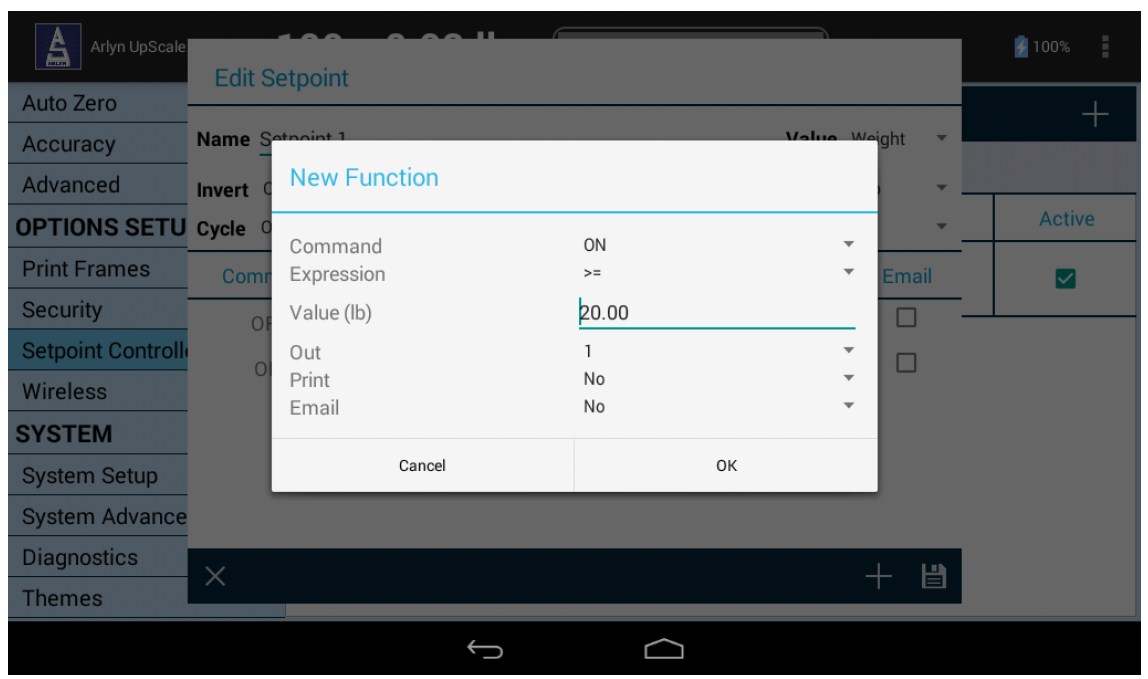
This section is similar to the Creating and Editing Formulas section. The only addition here is the specification for allowing the setpoint to email and/or print out the weight data when the weight condition in the command line is satisfied.
Select Yes/No for the Print option to print out a weight data frame on all connected outputs.
Select Yes/No for the Email option to email out a weight data frame to your specified email address on the main Setpoint Controller screen.
For the Print and Email option to work, the checkboxes for either of these options must be relevantly checked in the Setpoint Controller screen.
28.4 Setpoint Definition Screen (w/ Print and Email)
The Setpoint Definition screen has been enhanced to include Print and Email capabilities. In addition to the Output column, there is also Print and Email column. This allows you to quickly enable/disable the print and email option for the command lines.
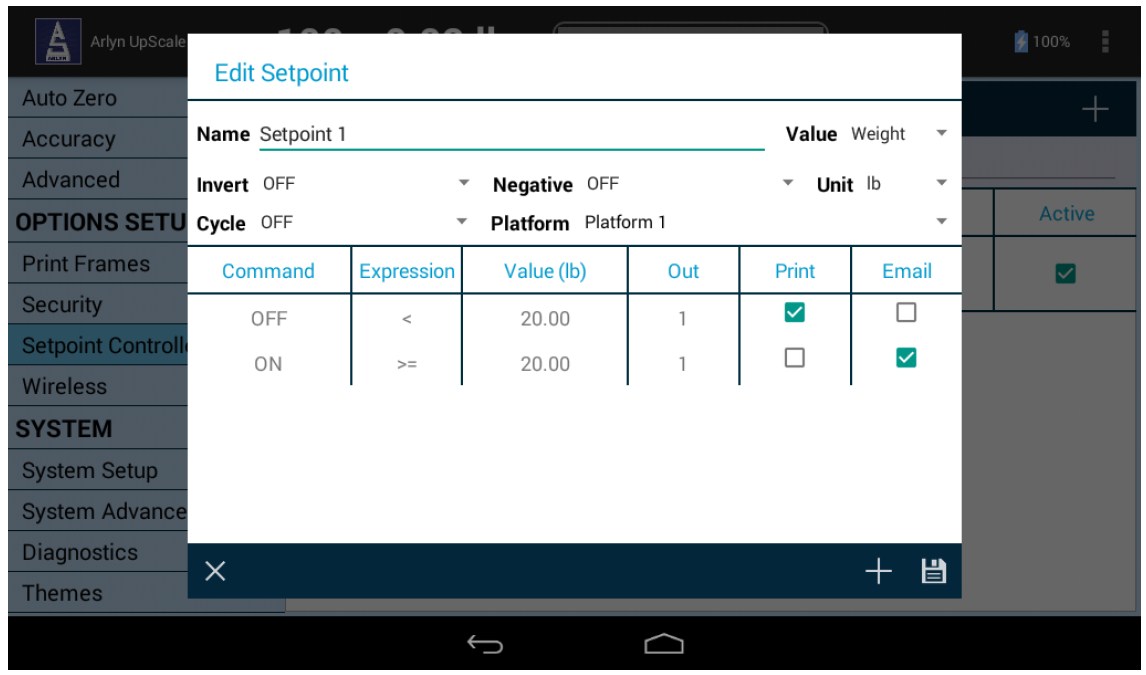
In the above screen:
• Line #1: Print Checkbox is enabled ? The scale will only print out a weight if the scale weight reads less than 20lbs. The print will be sent out once when LED 1 (Output 1) toggles OFF. The next print will only be sent if the LED changes state again (ON ? OFF)
• Line #2: Email Checkbox is enabled ? The scale will only email out the weight frame if the scale weight reads greater than 20 lbs. The email will be sent out once when LED 1 (Output 1) toggles ON. The next email will only be sent if the LED changes state again (OFF ? ON)
Caution: The email feature should be used very carefully. It is not intended to be used for quick setpoint triggers for very short-term weight changes (such as in a valve control environment, or check-weighing). If email is enabled for this purpose then you will spam your inbox with Setpoint emails and possibly cause the scale to undergo severe performance issues as it attempts to send out multiple emails in a short period of time.
The email feature is perfect for those cases where you want to monitor the weight of something for a long period of time. The intent to have the scale send you an email notification when it reaches your pre-defined target weight.
Typical Application: Keeping in mind the weights used in the screenshot above, suppose you have to monitor a cylinder of 50lbs and you want the scale to send you an email when it goes below 20 lbs. You would set up the Setpoints as in the screenshot above (there is no need to have the Print checkbox checked).
When the weight of the cylinder drains down to 20lbs, the scale will send out an email as soon as the 20lb threshold is crossed. This way, not only you can have an automated valve system refill your cylinder but you will also get a notification when it happens.
29 BARCODE / QR CODE SCANNING/PRINTING
29.1 Overview
The Barcode Feature, exclusively provided on scales upgraded with the Arlyn UpScale Indicators, provides our customers with the ability perform barcode functions without the need for dedicated barcode equipment such as a barcode scanner or a dedicated bar code printer.
Barcode Scanning (also applies for QR Codes)
Customers can use the Barcode Feature to scan barcodes using the indicator’s built-in camera system. You don’t need additional hardware (such as a barcode scanner) to perform this function. The Barcode Scanning feature is useful in Parts Counting. You can quickly search for a part definition on the scale to activated it for counting without going through a series of steps in the indicator menu system.
The Barcode Scanning feature is also useful for searching and activating tares of your containers without going through the indicator menu system. This allows for quick and easy changing of containers on the scale when needed.
Barcode Printing (also applies for QR Codes)
The Barcode Feature option also includes Barcode Printing. Barcode Printing is only supported with our 58mm Bluetooth and USB Thermal Printers. It is also supported using our select Star Micronics TSP Series label printers.
29.2 Usage
29.2.1 Printing Barcodes and QR Codes
For barcode printing to work, your scale must be setup with one of the supported printers that can be purchased at Arlyn Scales. The following printers are supported:
a) 58mm Bluetooth/USB Thermal Mini Printer
b) Star Micronics TSP Series Printer
The printers should have already been setup at factory with the default Print Frame (i.e. AFS_1008 for non-Parts Counting scales and AFS_1009 for Parts Counting Scales – See the Print Frames Section for further details) .
Simply press the PRINT button on the scale to bring up the “Select a Printer” dialog box:
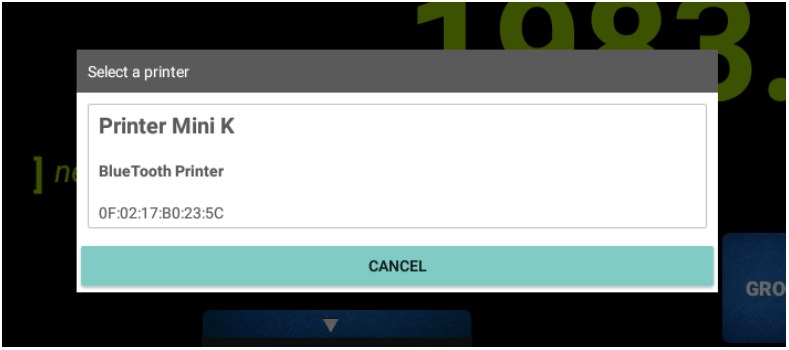
Press anywhere on the dialog box to confirm the print out. (Depending on certain settings, this can just show a “Printing” dialog box).
| Tare Barcode Printout | Parts Counting – Sample Barcode Printout |
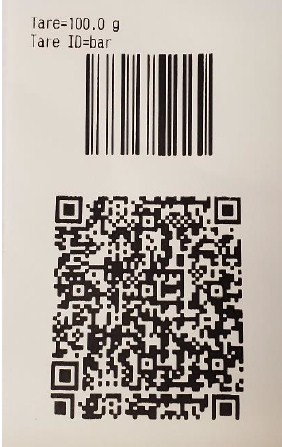 |
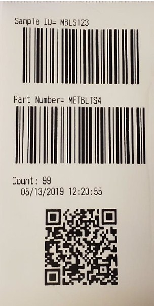 |
Please note that these printout formats are fully customizable – you can include more information or remove them, or change the placement of the barcodes.
29.2.2 Scanning Barcodes and QR Codes
Barcode scanning works for quickly retrieving Tares or Samples from the scale and activating them, instead of searching for them in the Settings Screens. Barcodes can also be scanned into Custom Fields Dialogs to quickly enter scanned alphanumeric codes into fields. For scanning barcodes, make sure you have some Tare Definitions or Sample Definitions already stored in the scale. The barcode to be scanned must represent a Tare ID or Sample ID/Part Number stored in the scale. Otherwise it will not work.
Follow the procedure below to scan a barcode entry.
a) Make sure that the indicator has a camera window at the bottom right-hand corner
b) Press and hold the UNIT button on the indicator to bring up the scanner. It should look like the screen below:
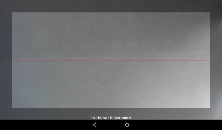
c) Place the bar code on the camera and make sure the barcode aligns with the red line on the screen.
d) Wait for a few seconds for the barcode to scan. If the scan is successful, a short beep will be heard. If the scan is not successful, the scanner will timeout and the indicator will go back to the main screen.
Depending on the scale type, a successful scan means that a stored “tare” will get activated. The screen will go into “Net Weight” mode.
If it’s a Parts Counting scale, a successful scan means that a store “sample” will get activated. The screen will be in Counting mode.
29.2.3 Storing Tares and Sample Definitions using Barcodes
With the addition of Barcode support, you can also use your existing barcodes in the process of storing Tare and Sample definitions in the UpScale’s internal storage.
For example, press the QuickAction menu on the top right corner of the screen and go to SETTINGS->TARE DEFINITITONS.
Press the ‘plus’ button on the top right corner near the search button. A “New Tare” Dialog will appear. Take note of the “Scan” button appear besides the “Name” field.
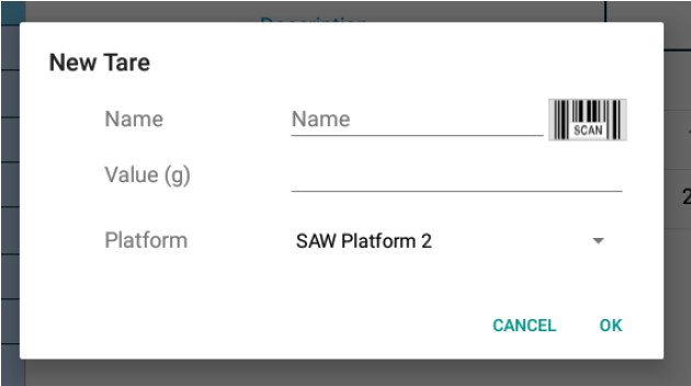
Press this button to bring up the scanner. Use that to scan your existing barcode and it will appear on the “Name” field. Put in the value of the tare and press the “OK” button to save it.
The process is similar for the Sample Definitions in Parts Counting scales.
30 MODBUS
Important Note: This feature is provided as a “Premium Feature (Beta)”. Please see terms and disclaimers regarding this and other premium features outlined in the Limited Warranty section.
The Arlyn UpScale can support multiple Modbus Communication modes depending on the medium of communication. It can perform:
a. Modbus RTU or Modbus ASCII (w/ RS-232, RS-485, RS-422 and USB)
b. Modbus TCP (Ethernet, Wireless)
30.1 Modbus Communication Configuration
To configure the Modbus Communication protocol, press the 3-dot Action Menu on the top right corner of the screen and select Settings.
On the left hand (blue) panel, scroll down to OPTION SETUP header. Then press the Modbus option.
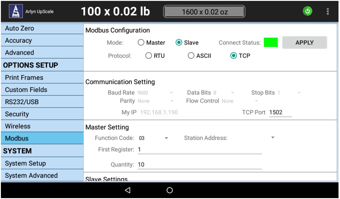
30.1.1 Transmission Modes
Use this region to select the desired Modbus Transmission mode.
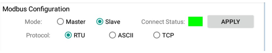
Mode
Master – Set the scale to be in Master Mode. [Not Supported]
Slave – Set the scale to be in Slave Mode.
Protocol
RTU – Remote Terminal Unit. This dictates the Modbus framework to transmit in Binary. This allows for greater density of characters which allows for the transmission of higher volume of data. Each byte (8 bits) in the message frame has 2 hexadecimal characters, 4 bits each.
ASCII – American Standard Code for Information Interchange. This mode allows for time intervals up to 1 second between characters during transmission without provoking an error. Each byte (8 bits) in the message frame is transmitted as two ASCII characters.
TCP – This mode is specifically for those applications that require Modbus TCP Protocol. This is only suitable for those scales equipped with Ethernet or Wi-Fi Communication options.
30.1.2 Communication Settings
Use this region to configure the Transmission parameters.
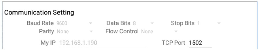
Serial Transmission (RTU/ASCII)
Use the following parameters to set Serial Transmission properties.
Baud Rate
Data Bits
Stop Bits
Parity
Flow Control
IP Address and Port (TCP)
If the transmission mode is set to Modbus TCP, and the scale is equipped with Ethernet or Wi-Fi, these parameters are relevant.
IP Address field will show the current IP Address of the scale as obtained from your network.
TCP Port is set to 1502. It can be changed to any number above 1000.
30.1.3 Master Setting [Not Supported]
The Master Mode on the scale is currently not supported.
30.2 Testing using Modbus Tools
To demonstrate the workings of Modbus protocol available with the scale, follow the procedures outlined below.
30.2.1 “Modbus Poll” Utility
The “Modbus Poll” program is a PC program used to test the Modbus output from a Slave Instrument. In this case, the scale is the Slave and the Modbus Poll program is the Master.
Download the utility.
1) Go to https://modbustools.com/download.html and download the Modbus Poll (32-bit or 64-bit depending on your PC).
2) Once downloaded, install the utility in your PC. Please note that this is a trial version that is available to you for 30 days. It can be operated 10 minutes at time.
3) Run it once to see if it is installed properly. Do not worry if it does not connect to your scale yet.
The Modbus Workspace
4) Arlyn had prepared a pre-configured workspace that already parses data incoming from the scale with minimal configuration. Proceed to https://www.arlynscales.com/modbuspollworkspace/ and download the workspace ZIP file.
5) Unzip the file and click on the “ModbusPollWorkspace.mbw” file.
6) This should open up the workspace with two windows.
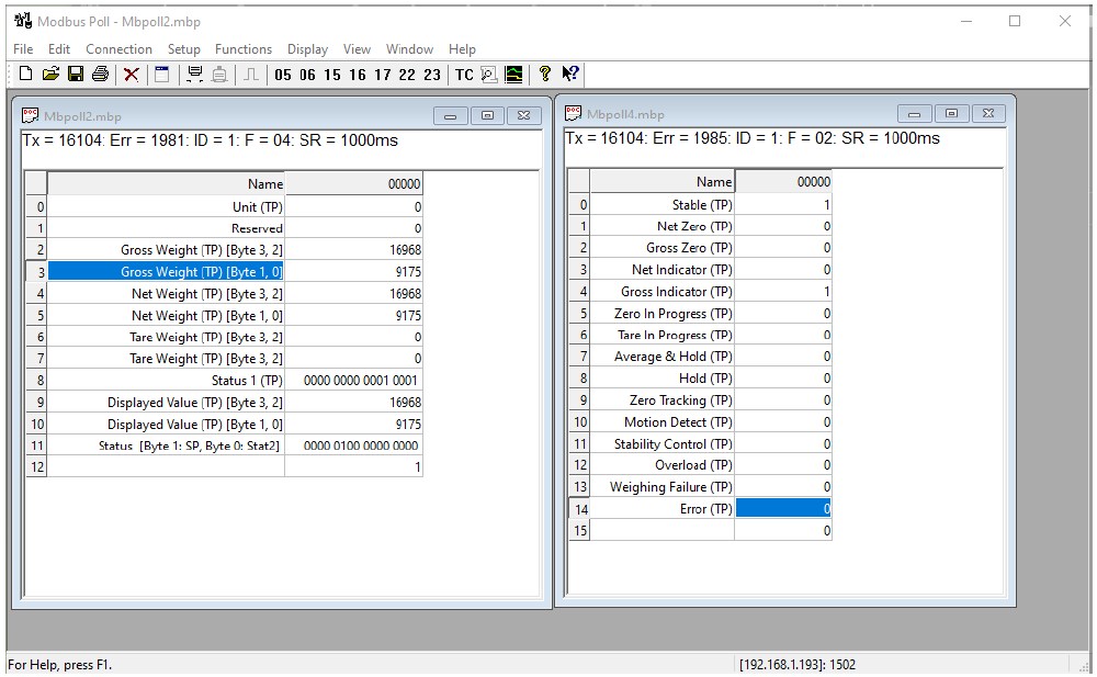
7) At this point, you may see Time out errors or No Connection errors. This is OK. We first need to connect to your scale.
30.2.2 Modbus RTU/ASCII
The Modbus RTU or ASCII protocol usually works through the Serial Communication medium. Follow the steps below to demonstrate this communication protocol.
1) Configure the scale for Modbus RTU or ASCII using the parameters described in Modbus Communication Configuration section.
2) Set communication parameters or leave them at default. The default parameters for serial communication are:
Baud Rate- 9600 bps
Data Bits – 8
Stop Bits- 1
Parity – None
Flow Control – None
3) Connect the scale to the PC (either through USB, RS-232, RS-485, etc).
4) In the Modbus Poll workspace, on the top Menu bar, click on Connection->Connect…
5) The “Connection Setup” screen is shown. Set the connection configuration as below.
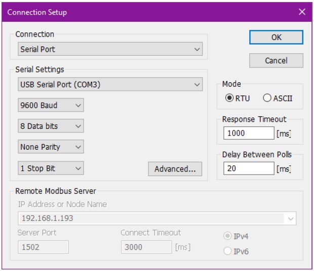
Please note the Serial Settings “COM port” needs to be according to what is shown in your Device Manager. This is the COM # assigned to your scale. For more details on determining your COM port assigned by the PC, see the sections RS-232 Communication Port or USB Communication (Virtual Serial Port).
6) For the “Mode”, you can choose to demonstrate RTU or ASCII. Please make sure that this selection matches whatever the configuration you have on the scale (Default: RTU).
7) Press OK to confirm.
If the configuration is correct and all the parameters are matched, you will now see activity in the MbPoll2 and MbPoll4 windows. Press on the platform to notice the data changing accordingly.
The next section describes testing the scale with Modbus TCP. If your scale is only equipped with Serial Communication, then skip this section and proceed to Data Areas.
30.2.3 Modbus TCP
1) Connect the scale to your Local Area Network (plug an Ethernet RJ-45 cable to the provided jack on the scale).
2) In the Modbus Configuration Screen select the Protocol to be Modbus TCP.
3) Make sure a valid IP Address can be seen in the “Communication Settings” on the Modbus Configuration Screen.
4) In the Modbus Poll workspace, on the top Menu bar, click on Connection->Connect…
5) The “Connection Setup” screen is shown. Set the connection configuration as below.
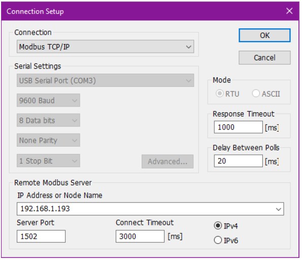
6) In the “Remote Modbus Server” group, type in the IP Address of the scale as shown in the “Communication Settings” in Modbus Settings.
7) Type in the Port number. The default is 1502 (as set on the scale).
8) Press the OK button to confirm.
If the configuration is correct and all the parameters are matched, you will now see activity in the MbPoll2 and MbPoll4 windows. Press on the platform to notice the data changing accordingly.
30.2.4 MbPoll (Monitoring) Windows
The MbPoll Windows shown in the Modbus Poll Utility Workspace demonstrates various active addresses in the scale from which data is being retrieved.
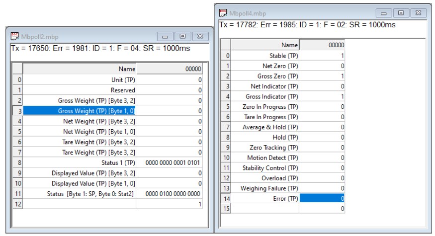
The Mbpoll2 window shown above shows data from registers addresses 30001-30013 (Function 04, Input Registers). The Mbpoll4 window shown above shows from register addresses 10001-10016 (Function 02, Input Status Registers, Bitwise). The complete address map of the Modbus protocol is illustrated in the Data Areas section.
30.3 Data Areas (Registers)
Data Areas are regions in the scale with address spaces, each containing specific data to be queried or written through Modbus protocol.
The scale has three data areas:
Input Registers (Address Region 30000) [Read Only]
Input Status Registers (Address Region 10000) [Read Only]
Coils (Address Region 00000) [Write Only]
Holding Registers (Address Region 40000) are currently empty. All the data available on the scale can be read using the registers mentioned above.
The Data areas outlined below only show a snapshot for a single platform scale without options. For a complete Spreadsheet with all the data points, download the register map here: https://www.arlynscales.com/modbus-mapping-v1/. Please note these addresses are subject to change.
30.3.1 Input Registers (Address 30000)
The Input Register Data Area is read by the Master (PLC) and written by the scale. Each address is a WORD (16-bits, 2 bytes). The address space starts from 30001.
| KIND | REG | ITEM | DESCRIPTION | NOTES |
| TOP PLATFORM | ||||
| ON | 30001 | Unit (Top Platform) | 0: lb, 1: kg, 2: g, 3: oz, etc. | |
| 30002 | Reserved | |||
| 30003 | Gross Weight value (Top Platform) | byte (3) | ||
| byte (2) | ||||
| 30004 | Gross Weight value (Top Platform) | byte (1) | ||
| byte (0) | ||||
| 30005 | Net Weight Value (Top Platform) | byte (3) | ||
| byte (2) | ||||
| 30006 | Net Weight Value (Top Platform) | byte (1) | ||
| byte (0) | ||||
| 30007 | Tare Weight Value (Top Platform) | byte (3) | ||
| byte (2) | ||||
| 30008 | Tare Weight Value (Top Platform) | byte (1) | ||
| byte (0) | ||||
| 30009 | Status 1 (Top Platform) | Data 16-bit “Input Status Registers”, 10001 to 10016 | ||
| 30010 | Displayed value (Top Platform) | byte (3) | ||
| byte (2) | ||||
| 30011 | Displayed value (Top Platform) | byte (1) | ||
| byte (0) | ||||
| 30012 | Status 2 (Top Platform) | Data 16-bit “Input Status Registers”, 10017 to 10032 | ||
| 30013 | Status 3 (Top Platform) | Data 16-bit “Input Status Registers”, 10033 to 10048 | ||
| 30012-30099 |
30.3.1.1 Input Register Notes
Format of GROSS WEIGHT, NET WEIGHT, TARE WEIGHT and DISPLAYED WEIGHT values
These values are presented in 4-byte Floating Point value. To read the whole weight, the 4 bytes presented must be interpreted as “floating point”.
Format of Input Status Registers
For redundancy measures, the Input Status Registers are presented here in 30009, 30012 and 300013.
30.3.2 Input Status Registers (Address 10000)
| KIND | REG | ITEM | DESCRIPTION | NOTES | |
| TOP PLATFORM | |||||
|
Coil Registers 10001 to 19999 (Slave-> Master) Bit Register (Each address maps to a bit) Status 1 – Top Platform (Also in Input Register 30009) |
010001 | Stable (Top Platform) | Bit 0 | 1: Green 0: Red | |
| 010002 | Net Center of Zero (Top Platform) | Bit 1 | 1: “zr” indicator in Net mode | w/ Motion/Detect | |
| 010003 | Gross Center of Zero (Top Platform) | Bit 2 | 1: “zr” indicator in Gross mode | w/ Motion/Detect | |
| 010004 | Net Display (Top Platform) | Bit 3 | 1: Display Showing Net | ||
| 010005 | Gross Display (Top Platform) | Bit 4 | 1: Display Showing Gross | ||
| 010006 | Zero in Progress (Top Platform) | Bit 5 | 1: Zero in Progress | ||
| 010007 | Tare in Progress (Top Platform) | Bit 6 | 1: Tare in Progress | ||
| 010008 | Average & Hold in Progress (Top Platform) | Bit 7 | 1: Average & Hold in Progress | ||
| 010009 | Hold (Top Platform) | Bit 8 | 1: Weight Hold 0: Normal | ||
| 010010 | Zero Tracking (Top Platform) | Bit 9 | 1: “Zero Tracking” in progress | ||
| 010011 | Motion Detect (Top) | Bit 10 | 1: Motion 0: No Motion | ||
| 010012 | Stability Control (Top) | Bit 11 | 1: Stable 0: Unstable | ||
| 010013 | Overload (Top Platform) | Bit 12 | 1: Overload 0: Normal | ||
| 010014 | Weighing Failure (Top Platform) | Bit 13 | 1: Weight cannot be shown for some reason. | ||
| 010015 | Error (Top Platform) | Bit 14 | 1: Error | ||
| 010016 | Bit 15 | ||||
| Status 2 – Top Platform (Also in Input Register 30010) | 010017 | Setpoint 1 | Bit 0 | 1: ON 0: OFF | |
| 010018 | Setpoint 2 | Bit 1 | 1: ON 0: OFF | ||
| 010019 | Setpoint 3 | Bit 2 | 1: ON 0: OFF | ||
| 010020 | Setpoint 4 | Bit 3 | 1: ON 0: OFF | ||
| 010021 | Setpoint 5 | Bit 4 | 1: ON 0: OFF | ||
| 010022 | Setpoint 6 | Bit 5 | 1: ON 0: OFF | ||
| 010023 | Setpoint 7 | Bit 6 | 1: ON 0: OFF | ||
| 010024 | Setpoint 8 | Bit 7 | 1: ON 0: OFF | ||
| 010025 | Bit 8 | ||||
| 010026 | HI Output | Bit 9 | (Weight or Parts Comparator) | ||
| 010027 | OK Output | Bit 10 | (Weight or Parts Comparator) | ||
| 010028 | LO Output | Bit 11 | (Weight or Parts Comparator) | ||
| 010029 | User input 1 | Bit 12 | |||
| 010030 | User input 2 | Bit 13 | |||
| 010031 | User input 3 | Bit 14 | |||
| 010032 | Bit 15 | ||||
| Status 3 – Top Platform (Also in Input Register 30011) | 010033 | Net over | Bit 0 | ||
| 010034 | Net under | Bit 1 | |||
| 010035 | Gross Over | Bit 2 | |||
| 010036 | Gross Under | Bit 3 | |||
| 010037 | Input (A/D) over | Bit 4 | |||
| 010038 | Input (A/D) under | Bit 5 | |||
| 010039 | Zero correction error | Bit 6 | |||
| 010040 | Tare error | Bit 7 | |||
| 010041 | Net display error | Bit 8 | |||
| 010042 | Bit 9 | ||||
| 010043 | Bit 10 | ||||
| 010044 | Checksum error | Bit 11 | |||
| 010045 | A/D error | Bit 12 | |||
| 010046 | FRAM error | Bit 13 | |||
| 010047 | Calibration error | Bit 14 | |||
| 010048 | Mode error | Bit 15 |
30.3.3 Coils (Address 00000)
The Coils Data Area can be used to send commands to the scale from the Master. For example, if you want to ZERO the scale from the Master (e.g. PLC), sent ON (or 1) to address 00001 and the scale will zero out. Similarly, the same can be said about changing units, or taring, etc.
| KIND | REG | ITEM | DESCRIPTION | NOTES | |
| TOP PLATFORM | |||||
|
Coil Registers 00001 to 09999 (Master -> Slave) Bit Register (Each address maps to a bit) Commands to be sent from the PLC to the Scale |
010001 | Zero (Top Platform) | Bit 0 | 1: Execute | |
| 010002 | Reserved | Bit 1 | Future expansion for Zero operation | ||
| 010003 | Tare (Top Platform) | Bit 2 | 1: Execute | ||
| 010004 | Clear Tare Value (Top Platform) | Bit 3 | 1: Display Showing Net | ||
| 010005 | Change Unit (Top Platform) | Bit 4 | 1: Toggle to next active unit | ||
| 010006 | Net / Gross Display | Bit 5 | 1: Net 0: Gross | 1: Toggle Net/Gross | |
| 010007 | Cycle (Top Platform) | Bit 6 | 1: Toggle Cycle (Abort Cycle) | 1: Toggle | |
| 010008 | Average Weight & Hold (Top Platform) | Bit 7 | 1: Start 0: Stop | 1: Toggle | |
| 010009 | Flow Rate | Bit 8 | 1: Toggle | ||
| 010010 | Log Weight | Bit 9 | |||
| 010011 | Bit 10 | ||||
| 010012 | Bit 11 | ||||
| 010013 | Bit 12 | ||||
| 010014 | User Output 1 | Bit 13 | 1: ON 0: OFF | NA | |
| 010015 | User Output 2 | Bit 14 | 1: ON 0: OFF | NA | |
| 010016 | User Output 3 | Bit 15 | 1: ON 0: OFF | NA | |
| 00017 – 00099 |
31 USER MANAGEMENT
Important Note: This feature is provided as a “Premium Feature (Beta)”. Please see terms and disclaimers regarding this and other premium features outlined in the Limited Warranty section.
The Arlyn UpScale Indicator offers the ability to control access to your scale and record usage of the scale as well as allow basic employee time management (in conjunction with other options such as USB, Ethernet, Wi-Fi, USB Datalogging, etc.) For example, when printing out data from the scale, you can determine who was logged in to the scale when work was performed. This can be determined by the username and timestamp printed out on each weight line.
31.1 Overview
To access the User Table, use the Quick Action Menu to go to SETTINGS?SYSTEM?USER MANAGEMENT.
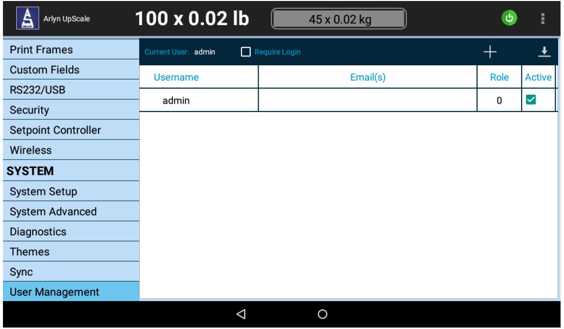
Note: If you do not see all the fields in this table, “drag” the screen to the right to view more fields.
TABLE FIELDS
Username The username of the user
Email(s) Relevant email or emails of the user
Role The assigned role of the user (currently not effective – for future expansion)
Active If the user has access to the scale
CURRENT USER – Current logged in User
LOGIN REQUIRED – Check this to force a Login Dialog to appear at every reboot.
The current default user has been added as “admin”. The default password for this user is also “admin”. It is strongly recommended to change this password if the User Management Feature will be used for your production to avoid unauthorized access to the scale.
31.2 Logging In
Once the user has been setup, select the “Require Login” check. Go back to the main screen and reboot the scale.
Once the scale is rebooted, a Login Dialog box will popup to prompt access to the scale.
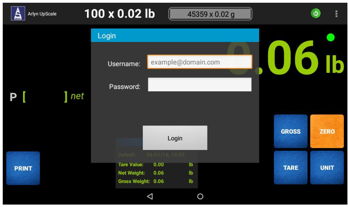
If no user has been previously set up, enter the following credentials to login into the scale:
Username: admin
Password: admin
If the user table has been setup and/or if the admin password has been changed, enter your set password to gain access to the scale.
Failing to enter the correct credentials will not allow access to the scale.
31.3 Managing Users
The following screen presents the User Table again with additional users added in for illustration. This section will cover methods to add, edit and remove users from the table.
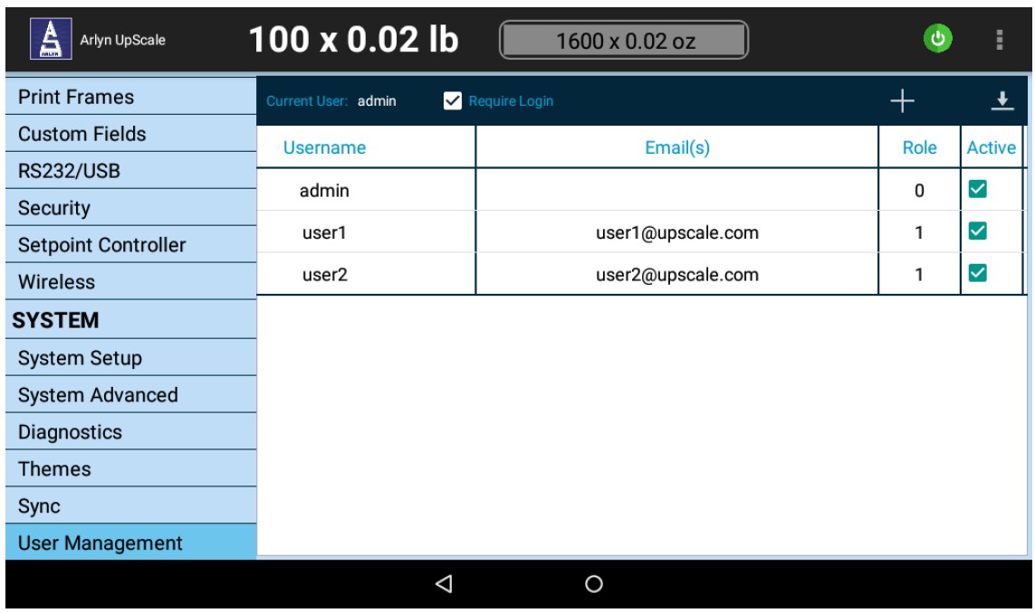
31.3.1 Adding New Users
To add new users to the table, press the ‘+’ symbol on the top right corner of the table bar. This will bring up a the “Add New User” dialog.
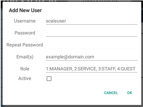
| Username | Enter the username of the person who will be logging into the scale. This username will be used in printouts and datalogs if the user is logged into the scale. |
| Password | Enter the password for this user. |
| Repeat Password | Confirm the password for this user. |
| Email(s) | An email address (or multiple email addresses) can be entered optionally for this user for future tracking or notification. This is reserved for future expansions (or will be implemented on customer request) |
| Role | Enter any number between 0-4. This field would determine access level for the user being added. At the moment, this field is ineffective. Essentially all users entered will have full access to the scale. It’s a place holder for future expansion (or will be implemented on customer request). |
| Active | Place a check here if you want this user to be able to access the scale. If the user needs to be locked out, uncheck this field. |
Press OK to save the user to the scale database.
31.3.2 Editing Users
To edit an existing user, press the user record you want to edit in the User Management table to bring up the Edit User Dialog.
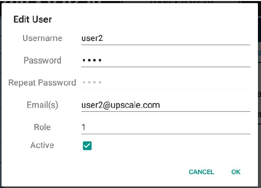
This dialog is equivalent to the “Add New User” dialog except that the user’s information has been prefilled. Proceed to modify any information here and the press OK to save the user to the scale database.
31.3.3 Deleting Users
To remove a user or multiple users from the list, press and hold a single user record from the table. Then proceed to select other users who you also want to remove from the table. Once you finish selecting all the users you want to remove from the table, press the Delete button (Garbage can icon) on the top right corner of the table – as shown below.
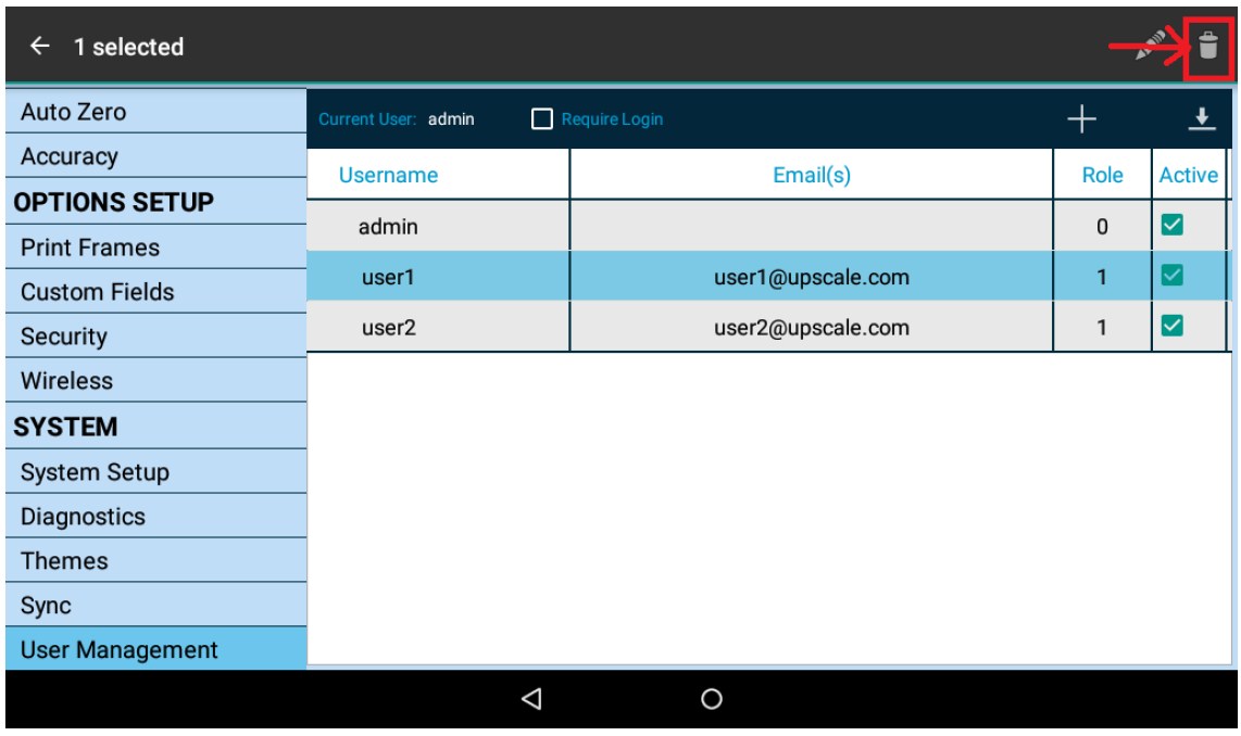
A confirmation bar appears at the bottom of the screen as seen below:
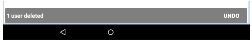
Press the “UNDO” button to restore deleted records if desired.
31.4 User Tracking, Printing and Data Output
The User Management system is a powerful tool that can be used to track usage of the scale when combined with any of the digital outputs available with the scale.
One of the Print Frames that outputs the username of the user is AFS_1007 (See Print Frames section). This print frame has the following format:
Username: [TB_UNAME], [Date][Time], [Gross Weight] [Unit], [Net Weight] [Unit] [CR/LF]
? where TB_UNAME is the current logged in username.
Once the user is logged in, pressing the PRINT button (or querying the scale with the PRINT command) will first print the username of the authenticated user followed by the time stamp and some weight data. See the terminal output below as an example.
Username: user1, 08/03/2018,17:51:20,10.70 lb,10.70 lb
In the above example, user1 was logged in and at 08/03/2018 at 17:51 hrs., a gross weight of 10.70 lb was recorded. With output messages like this, an organization can track productivity time of personnel operating the scale.
Please note this format can be customized by the factory. Please call the factory for any additional data or formatting requirements
31.5 Logging Off
To log off the scale, click on the Quick Action Menu button on the top right of the main screen to bring up the Quick Action Menu. Press the “Log Off” option to log off the scale.
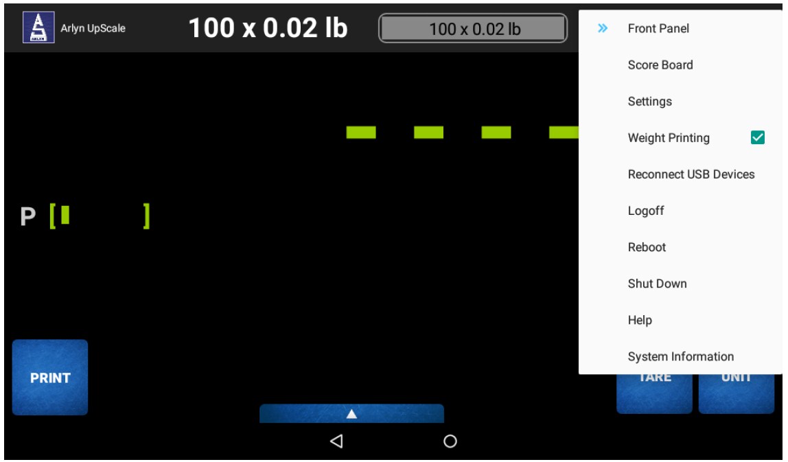
This will result in the Login Screen dialog showing on the screen so that the next user can login for the next shift.
32 CUSTOM FIELDS
Important Note: This feature is provided as a “Premium Feature (Beta)”. Please see terms and disclaimers regarding this and other premium features outlined in the Limited Warranty section.
The Custom Fields Feature allows our customers to define and extend data fields to be printed or recorded from the scale that are not part of the weight data matrix.
The scale can print out or record a range of metrological data available at its arsenal. For example, it can print out current weight, net weight, gross weight, tare weight, tare weight description, time, date, weight number, unit, piece count, sample piece description, etc. Notice that all the data listed here are related to weight in some way or the other.
But suppose you deal with fruits as your trade. How do you print or record what fruit was being weighed at the time in addition to the weight recorded? How do you choose the color of the fruit being weighed? What if you wanted to print or record whether the fruit was ‘Organic’ or ‘GMO’? The Custom Field Feature allows to print or record additional information about the weight being measured.
All Arlyn UpScale Indicators have this feature as standard – no additional purchases required (except for the output option itself).
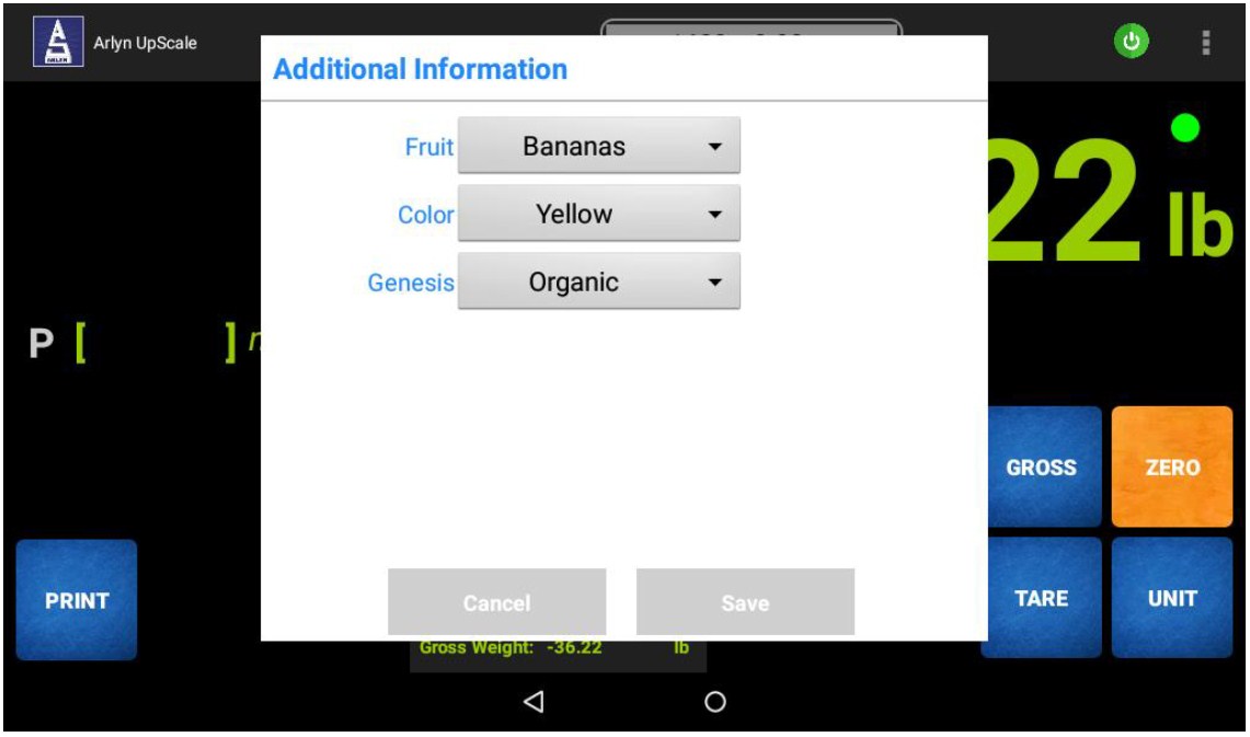
32.1 Overview
The Custom Fields Settings can be accessed by pressing the Quick Action Menu button and going to SETTINGS?CUSTOM FIELDS.
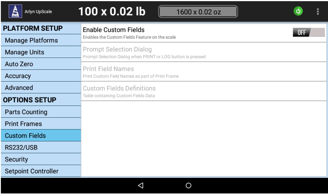
In the Custom Fields Settings Panel, there are four items available:
Enable Custom Fields
Turns on the Custom Fields Feature
Prompt Selection Dialog
Enables the process where the Custom Field Selection Dialog appears every single time the PRINT or LOG button is pressed.
Print Field Names
Prints out the “Field Name” along with its value at every print out.
Custom Fields Definitions
Data table containing Field names and values to setup the Selection Dialog.
32.2 Custom Field Settings
32.2.1 Enable Custom Fields
This item turns on the Custom Field feature on the scale. Once this feature is on and properly set up, the scale will print out the additional fields at every Print Frame – regardless of the Print Frame chosen in Print Frames Settings.
To turn on Custom Fields, use the switch on the right of the item and toggle it to ON. This will turn on the rest of the Custom Field Setting items.
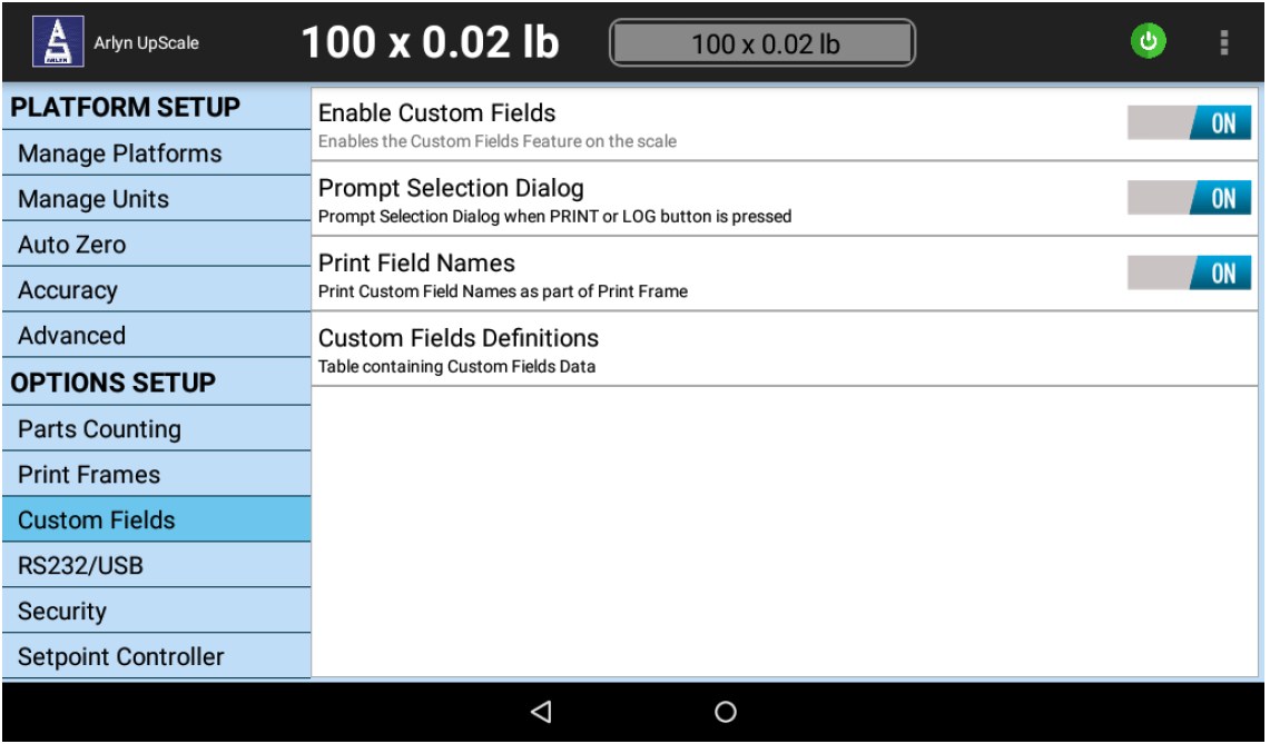
32.2.2 Prompt Selection Dialog
The Selection Dialog is the dialog seen after a Print or Log button is pressed on the main weight screen (see the Overview Section of this chapter). In most cases, the Selection Dialog should appear each time the PRINT button (or LOG button) is pressed, so that the operator can select the fields appropriate to the weight being printed out.
In some cases, if a product of the same characteristics is being weighed in a batch process, then the Selection Dialog is not needed. It is only needed the first time it appears and then it should be toggled off until a new batch with new product is weighed.
For example, if you are going to be weighing Organic Yellow Bananas for the next 1,000 weighing sessions, then the Selection Dialog should only be toggled once. The characteristics of should be selected once and saved and then the toggle button for this setting should be turned OFF. Now the same characteristics will be printed out over and over again until the settings are changed in the next batch.
NOTE: The Selection Dialog will not appear if Remote Command (i.e. ~*P*~) is sent to the scale. In this case, the saved characteristics in the Selection Dialog will be printed continuously until the characteristics are changed.
32.2.3 Print Field Names
This setting allows you to print the Field Names (or Categories) along with the values. Basically, consider the screenshot below:
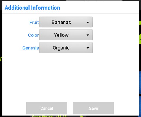
If the ‘Print Field Names’ setting is turned ON, then the print out will appear like this:
Fruit: Bananas, Color: Yellow, Genesis: Organic, 10.70 lb
If the ‘Print Field Names’ setting is turned OFF, then the print out will appear like this:
Bananas, Yellow, Organic, 10.70 lb
Depending on your requirements, you have the ability to control this feature regardless of the Print Frame Format you selected in the Print Frames setting.
32.2.4 Custom Fields Definitions
Custom Field Definitions is a set of Custom Fields and their properties stored in the data table. You can manage your Custom Fields using this table and create a meaningful system to document and manage your production.
Press the Custom Field Definitions setting item to reveal the Custom Field Table.
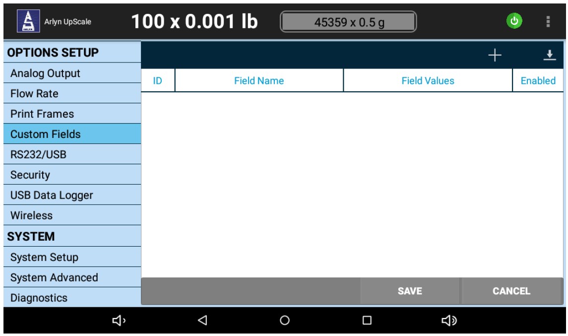
By default, the table is empty. The screenshot below shows a filled table as an example.
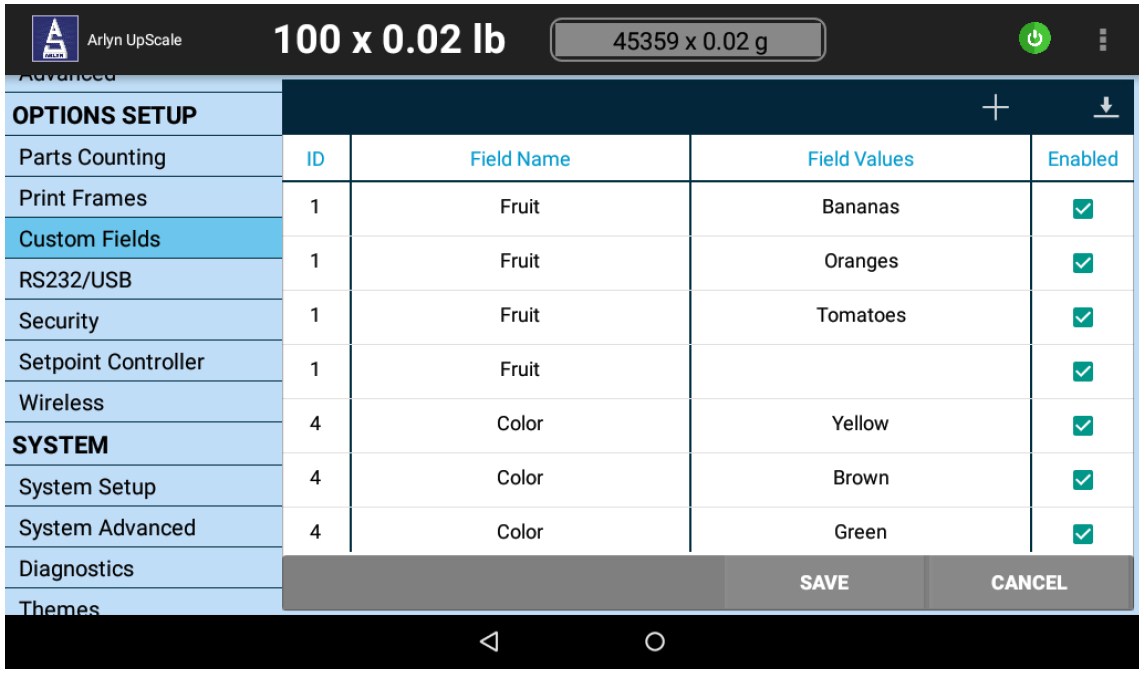
A full view of this example is given below.
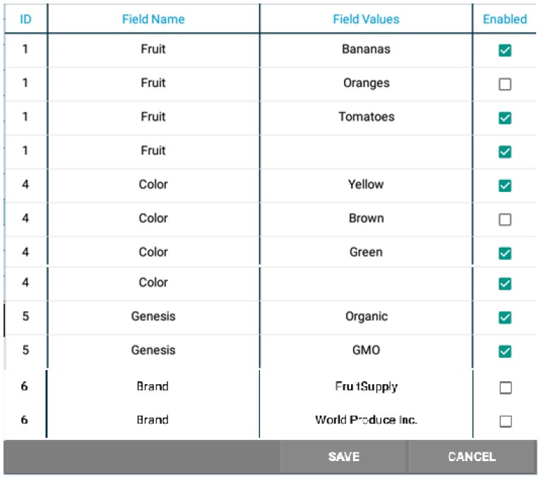
32.2.4.1 Columns
ID
The ID of the Field Name
Field Name
The name of the field (or category) under which the field value will be aggregated
Field Value
The value entry of the field as a selection.
Enabled
Enable the field/selection.
32.2.4.2 Table Example – A Study
• The table contains 3 categories (or Field Names) – Fruit, Color and Genesis. Here is a revisualization of the table:
| Fruit | Bananas, Oranges, Tomatoes |
| Color | Yellow, Brown, Green |
| Genesis | Organic, GMO |
| Brand | FruitSupply, World Produce Inc. |
• Fruit and Color has a ‘Blank’ value as a selection but Genesis does not. With a ‘Blank’ or ‘Empty’ value, the operator has the option to not chose any value in the given list for that field – making the field a text box for typing in values instead of a drop-down selector.
• The Genesis Field has no ‘Blank’ value, meaning that the field is Required and the operator must choose the correct value before printing.
Page | 99
• The ‘Orange’ value in the Fruit category is not enabled. In the same way, the ‘Brown’ value in the Color category is not enabled either. This means that even though these values have been entered in the table, they will not appear in the Selection Dialog on the main screen.
• The Brand Field Name has both of its values disabled i.e. ‘FruitSupply’ and ‘World Produce Inc.’ This means that since all available values for this Field Name are disabled, this entire field will not appear in the Selection Dialog.
The next sections describe how to manage the data in the custom fields table.
32.2.4.3 Add New Field
To add new fields to the table, press the ‘+’ symbol on the top right corner of the table bar. This will bring up a the “Add New Field” dialog.</p >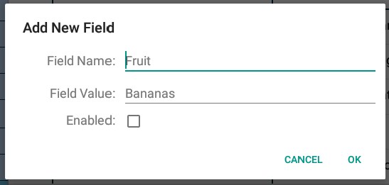
Field Name
Enter the name of the field for this value. Entering an existing Field Name will add the following Field value under that name in the Selection Dialog.
Field Value
Enter the value for this Field Name. This field can also be left ‘Blank’ (if you do not already have a ‘Blank’ Field within the existing Field Name). With Blank Field Value, the field becomes a Text Box that be used for typed in values.
Enabled
Check this box if you want this Field Value to appear in the Selection Dialog.
Press OK to save the field to the scale database.
32.2.4.4 Editing Fields
To edit an existing Field Value, press the field value record you want to edit in the Custom Fields table to bring up the Edit Field Dialog.
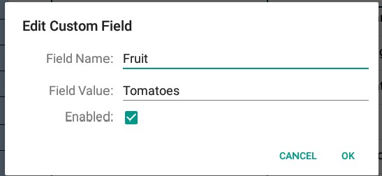
This dialog is equivalent to the “Add New Field” dialog except that the field’s information has been prefilled. Proceed to modify any information here and the press OK to save the field to the scale database.
32.2.4.5 Deleting Fields
To remove a Field Value or multiple Field Values from the list, press and hold a single field value record from the table. Then proceed to select other field values you also want to remove from the table. Once you finish selecting all the field values you want to remove from the table, press the Delete button (Garbage can icon) on the top right corner of the table – as shown below.
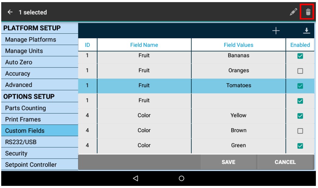
A confirmation bar appears at the bottom of the screen as seen below:
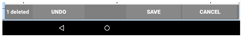
Press the “UNDO” button to restore deleted records if desired.
Please note: if all the Field Values are deleted that pertain to a single Field Name, then that field will cease to appear in the Selection Dialog.
32.3 Custom Field Printing and Data Output
This section has been touched upon in the Overview as well as the Print Field Names Section of this chapter. Once the Custom Fields have been setup and enabled, every time the operator presses the PRINT button or the LOG button, a Selection Dialog will pop up prompting the operator to select additional information to append to the outgoing Print Frame.
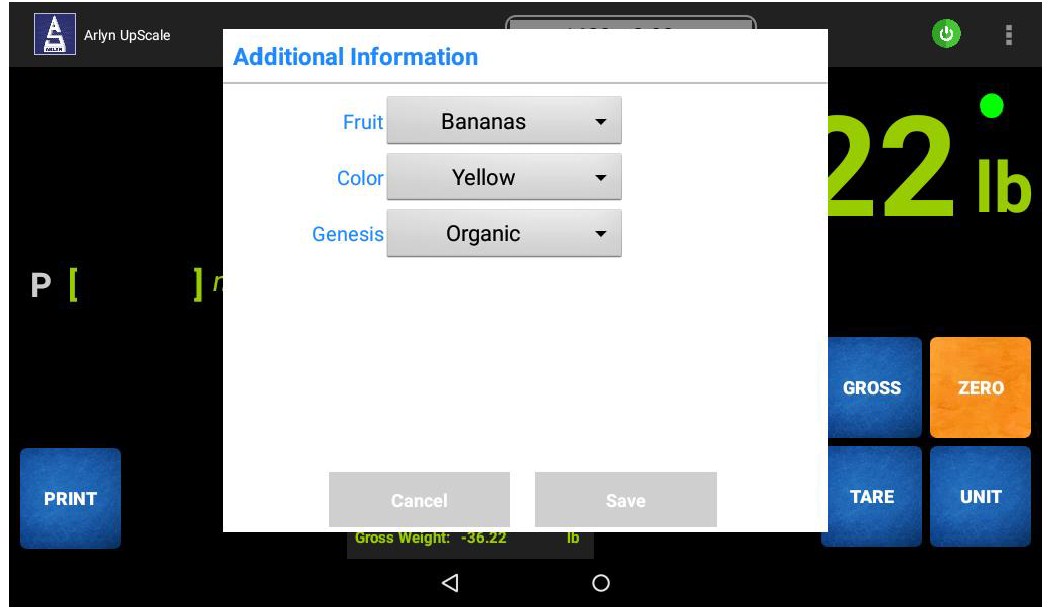
Once the selection is made, the operator presses the SAVE button. At this point, the data is sent to the output medium (RS232, USB, Ethernet, Wi-Fi, etc.)
Depending on the Print Frame selection, the field values will be prefixed to the Print Frame. The output below is an example if the Print Frame AFS_0004 is selected.
Fruit: Bananas, Color: Yellow, Genesis: Organic, 08/07/2018 10:30:21, 36.22 lb, 36.22 lb net
Please note this format can be customized by the factory. Please call the factory for any additional data or formatting requirements.
32.4 Custom Fields and Barcode Scanning
The Arlyn UpScale has the ability to be equipped with Barcode Scanning and Printing features. The scanning is accomplished by using the display’s camera feature. You can scan barcodes into a text field on Custom Field Dialog boxes by pressing the “SCAN” button on the field. This will bring up the Barcode Scan screen. Scan the code and it should automatically appear on the screen.
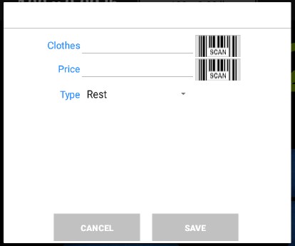
Learn more in the Barcode Scanning and Printing Section.
33 DATA LOGGING – SPECIAL FEATURES
Important Note: This feature is provided as a “Premium Feature (Beta)”. Please see terms and disclaimers regarding this and other premium features outlined in the Limited Warranty section.
33.1 Send Data Logs via Email (w/ Wi-Fi or Ethernet Option)
Once a Data logs are available, you can use this option to send the logs out to your email. This function is only available for indicators with Wi-Fi or Ethernet equipped together with the Datalogger option. The Wi-Fi or Ethernet must be pre-configured before setting up the email portion. Please see the Wi-Fi or the Ethernet section for further details on setting up your scale for internet connectivity.
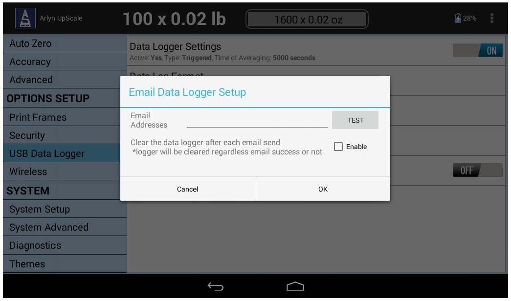
Before sending out emails, the Datalogger setup must be configured for sending out emails. To do this, do the following:
a) Long Press the “Send via Email” selection to bring up the Datalog Email Configuration screen.
b) Enter your email address on the space provided.
c) Press OK. You can also press the TEST button to see if an email arrives at your inbox.
d) You can even set the datalogs to be cleared once an email has been sent out. Set the Enable checkbox to do this. If this checkbox remains unchecked, logs with old data will also be included in the email attachment.
Once the email has been set up, log some data from the Front Panel. Then come back to this screen and just press the “Send Via Email” selection. An email will be sent out immediately with the logs of your scale. This way, you can send emails on demand.
33.1.1 Schedule to Send Data Log Email (W/ Wi-Fi Or Ethernet Option)
You can also send emails out automatically after a certain period of time. The scale is designed in such a way that you can set a specific time either by the minute going up to on a weekly basis.
To do this, simple click or Long Press the “Schedule Email” selection on the Datalog setup screen.
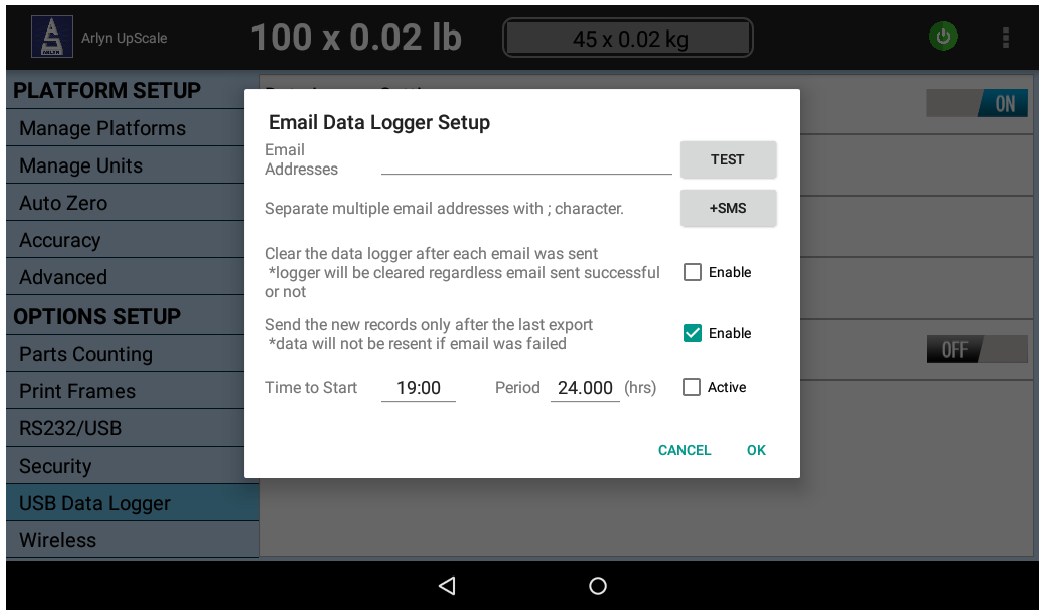
a) Enter the email address you want the email to be sent to. Press the TEST button to check if the email arrived in your inbox.
b) Set Time to Start – The time at which the first email should be sent out.
c) Optional – The “Clear Datalog” Enable checkbox. Set the datalogs to be cleared once an email has been sent out. If this box remains unchecked, logs with old data will also be included in the email attachment.
d) Optional – The “Send New Records Only” Enable checkbox allows the scale to send the latest records that were logged after the last exported records. This does not clear the database table.
e) Set the Period – The next and subsequent emails to be sent after this period. This time should be specified in hours. You can even use fractional numbers (0.5 hrs or 0.2 hrs) to specify minutes. These will be approximated to the nearest minute.
f) Set the Active checkmark – Enables the scheduled email feature.
g) +SMS – Allows the datalog file to be sent to a cell phone through SMS – Follow instructions on the following screen to set up your phone to receive the data
33.2 Import/Export Database Definitions
If you have a separate database of tares or parts (for Parts Counting) that can be exported out an Excel Spreadsheet or CSV file, the Arlyn UpScale indicator (equipped with USB Data Logger function) can import those records instead of manually entering them on the scale screen. This way, hundreds of definitions can be imported into and exported out of the scale’s fully editable and searchable database instantly. This function can also be used to import/export data out of multiple scales to synchronize databases between scales.
33.2.1 Pre-Requisites for Import/Export
Before performing the Import function, the following prerequisites must be met.
a) it is imperative to know if your parts or tare database is exportable into an Excel or CSV format. This is required to merge your CSV file to the scale’s CSV file before import.
b) The CSV file to be imported into the scale has a rigid format. Your exported CSV file must match the fields of the scale’s CSV file for the import to work. There are many third-party tools available for mapping and merging CSV/Excel files. Some of them are:
? https://www.ablebits.com/excel-lookup-tables/howto-merge-data.php
? https://www.office-addins.com/-excel-addins/lookup-assistant.php
It is the customer’s responsibility to match the format of their CSV files they wish to import to be compatible with the import requirements of the Arlyn UpScale, either through the add-ons mentioned above or some other means. Arlyn is not responsible nor liable on the reliability or the functionality of the software mentioned above.
33.2.2 Import/Export Procedure
The following steps describe how to successfully import your tares or parts table into the Arlyn UpScale indicator. These steps will use the Samples table (available with Parts Counting scales) to demonstrate import/export feature of the indicator.
33.2.2.1 EXPORTING DATA
a) Firstly, it is easier to start with exporting the current sample (or tare table) from the indicator. It is also strongly recommended to export the current table from the indicator before doing an import. This will “backup” the current table on the indicator in case anything goes wrong during the import process.
b) Insert a suitable USB stick into the USB Data Logging port. It is recommended to use the factory provided USB stick as it has been formatted to be recognized by your scale as well as your PC.
c) Navigate to the table you want to export and touch the “Import/Export” icon at the top-right corner of the table.
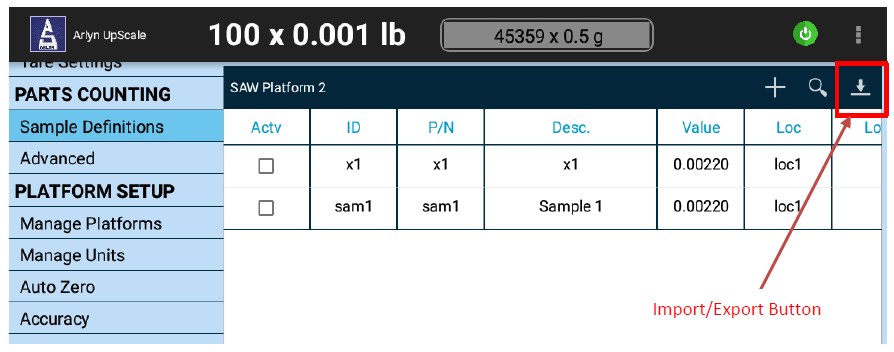
d) This will bring up the “Data Table Import/Export” Dialog.
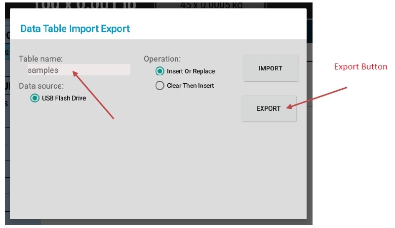
The Dialog will indicate which table is about to be exported under the “Table Name” field. Since we are demonstrating exporting Sample Definitions, the Table Name field is showing “samples”. If the Tare Definitions are being exported, the Table Name Field will show “tares”. Press the “EXPORT” button to export the current table into the USB stick.
e) Wait for the operation to complete – you will notice the “Export Successful” notification appear on the screen.
f) Pull the USB stick out and plug it into your PC. The illustration below uses a Windows PC to demonstrate file locations and other items.
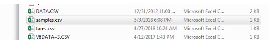
Copy the “samples.csv” file out to a safe location in your PC as backup. You can also rename this file to “samples-org.csv” or any other suitable name so that it doesn’t get overwritten on the next export process. Note: If you have exported the Tares table, then you will see the “tares.csv” file.
33.2.2.2 MAPPING FIELDS
g) Open the “samples.csv” to view it.
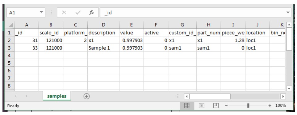
Basically, the CSV file is a snapshot of the scale’s database table. The essential fields to note here are the “description” column, the “value” field and the “custom_id” field. The rest are not essential. Even the “_id” field can be left blank for the scale to populate.
h) Use this “samples.csv” file to map the columns in your custom database export. This can be done with the help of the tools mentioned in the Prerequisites Section, or by other means.
i) Below is an example of a mapped “samples.csv” file with new parts added but using the same column names and order of columns.
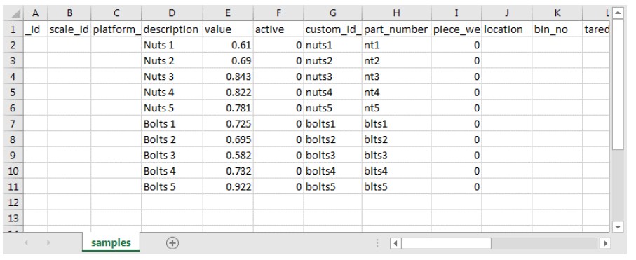
Notice that only the “description”, “value”, “custom_id” and “part_number” fields have been populated. The “part_number” field is optional but it has been filled regardless. The rest of the fields have been kept blank. However, they maybe filled if required.
Notes:
The value is always in “grams”. If you have data in any other unit, it must be converted to “grams” when stored in the CSV file to be imported.
It is important to keep the “_id”, the “scale_id” and the “platform_id” fields blank when adding new parts. This will be filled by the scale.
It is important that the order of the fields and the field names remain unchanged. Save the “samples.csv” file into the USB stick.
It is important that if your export function includes “_id”, then these values should not be repeated or overlapped. Otherwise
33.2.2.3 IMPORTING DATA
j) Plug the USB stick with the new “samples.csv” file back into the scale and touch the “Import/Export” button again on the top right corner of the table. This will open the “Data Table Import/Export” Dialog.
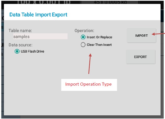
k) There are two types of Import Operation:
a. Insert or Replace – This operation will insert the records from the CSV file into the scale data table without affecting previous records. It will also attempt to replace (i.e. update) the existing records with modified data on the same “_id”.
For example, in item (g) above, if you decide to rename the description for ID = 31 from “x1” to “fort2”, then the import function will replace those fields with the updated records without inserting an entire new record.
b. Clear Then Insert – This operation will clear all the data on the existing table in the scale before importing new records. This is recommended to do if you are importing the new data for the first time. This operation can also be used to update the data in the scale, but the existing table must be backed up, updated and then re-imported with new data.
Selecting this function will produce a warning on the dialog:
“DATA LOSS WARNING: This function will clear the scale’s data table first and then import the data from the USB stick. If the import fails, the previously cleared data will be permanently lost. It is strongly recommended to backup the current table by doing an EXPORT in a separate file in your USB stick, then use the Import function. If the data import fails, you can easily restore your previous data by importing the original file.”
l) For this operation, we will select “Clear Then Insert”. Pressing the Import Button will now import all the data in the table. Wait for a few moments until the “Import Successful” message appears. If there are errors during the “Import” process, it will appear in red on the dialog.
m) Go back to the data table and verify that all the parts have been imported successfully.
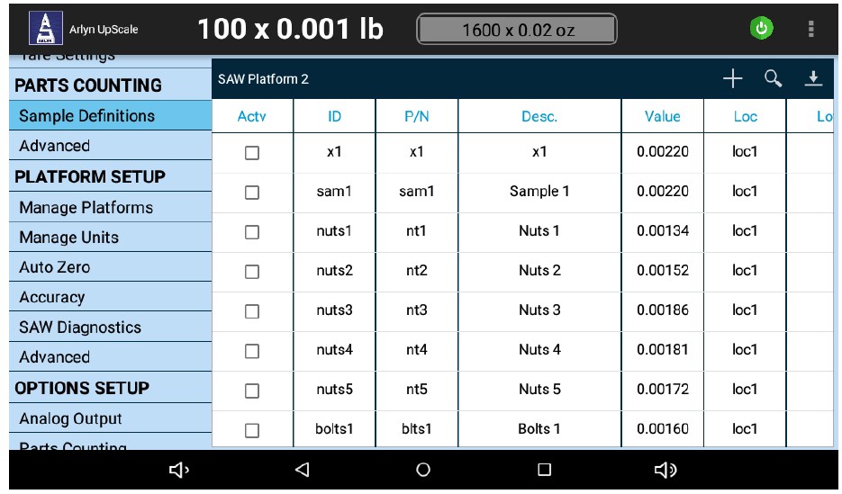
Since we picked “Insert or Replace”, the previous records are still there while new ones have been added from our new CSV file. The unit of the value will reflect what the current active unit is on the main weight screen.
n) This completes the Import operation.
33.3 Data Logging with Google Spreadsheets
Please note, this feature is only available if the Arlyn UpScale is equipped with USB Datalogging Option and any of the TCP/IP options (WiFi or Ethernet). Even though the USB Datalogging Option calls for ‘USB’, no USB hardware is required for this feature to work.
In addition to logging data locally (i.e. internal database and exported to USB stick), the Arlyn UpScale also features the ability to log data directly online, into a Google Spreadsheet. The logging of data can be observed almost in real time (allowing for a 2 second delay due to the time it takes for the data to be posted to the internet).
Any Google Spreadsheet can be used to implement this feature as long as edit permissions have been set appropriately. Use the steps below to create and configure a Google Spreadsheet to accept data.
33.3.1 Benefits
Using a live Google Spreadsheet for Data Logging is especially useful for customers who want to view their scale data logging live anywhere at any time. It’s a simple replacement of complex and rigid web logging method that is still being used by other scale vendors.
Here are other benefits of live Google Spreadsheet logging.
- View incoming scale data from anywhere in the world.
- Share incoming live data with anyone who has the Google Spreadsheet link
- Perform live analysis of incoming data such as daily weight increase and weight distribution.
- Use full spectrum of Google Spreadsheet capabilities and add-ons on incoming data. No proprietary software needed.
- No need to wait until the end of period before exporting data from scale.
A demonstration of live Google Spreadsheet logging can be seen here: https://youtu.be/xxURKe_TWuo
33.3.2 Limitations
- Google Spreadsheet logging will only work if the scale is connected to the internet through WiFi or Ethernet.
- If the internet is disconnected, the scale will continue to log into its own internal table. This can be later exported through email or using a USB Flash Drive.
- Google Spreadsheet logging is slower than local Scale logging due to the delay in opening a connection to the internet and posting the data on the spreadsheet.
- Google also has fallback rate limits. If the logging happens too frequently, then the Google Spreadsheet engine throttles incoming data speeds. Experiments show that setting the log period at 10 seconds is appropriate. Any period faster than that will not work.
- Google Spreadsheet must be initiated through an account first. Once the spreadsheet has been initialized, it can then be set to be accessed by anyone with the link to the spreadsheet.
33.3.3 Setup
Follow the steps below to setup a Google Spreadsheet and the Arlyn UpScale for live Data Logging.
33.3.4 Part I: Create a Google Spreadsheet for UpScale Data Logging
1) Create a Google account (if you do not have one).
Google only allows creation of a Spreadsheet through a Google account. Once the account is created and the Spreadsheet is generated, the Spreadsheet can be accessed and used by anyone as long as the privacy settings have been set correctly.
2) Create a new Spreadsheet.
a. Go to Google Drive.
b. In the “My Drive” menu, select “Google Sheets” and create a new spreadsheet.
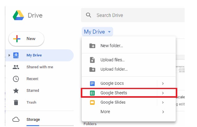
3) To allow the Google Spreadsheet to capture data through the internet, a script program must be embedded into the sheet. See the code below. The code is available under Software Downloads section on the Arlyn Scales website. https://www.arlynscales.com/software-downloads/. Look for the “Google Spreadsheet Script for Datalogging” file and download it. To add a script to the Google Spreadsheet, follow the steps below.
a. In the Spreadsheet menu, click on “Tools” -> “Script Editor”. This will open a new window/tab with a editable code page.
b. Select all text in this page and delete it.
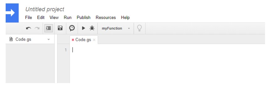
c. Go to https://www.arlynscales.com/software-downloads/.
d. Look for the “Google Spreadsheet Script for Datalogging” file and download it.
e. Open the downloaded text file.
f. Copy the text from the text file in (e) Step 3 above and paste it in the code page.
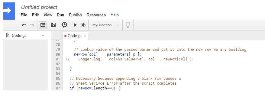
4) Publish the script as a Web App.
a. Once the code has been pasted in, go to the Script Window menu and press “Publish” -> “Deploy as web app..”
b. A dialog box will pop up prompting to name the script project. Enter the name of the project, something like “V9Script” or “GsScript”. Press OK.
c. After pressing OK above, the “Deploy as web app” dialog pops up.
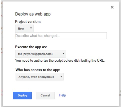
d. In the “Deploy as web app” dialog, fill in the following:
i. Project Version: New (leave the description field blank)
ii. Execute the app as: Me (or the current logged in account)
iii. Who has access to the app: Anyone, even anonymous
e. Once done, hit the “Deploy” button.
f. Depending on the security settings of your browser, you might get certain warnings. You will get a warning that the app is not verified.
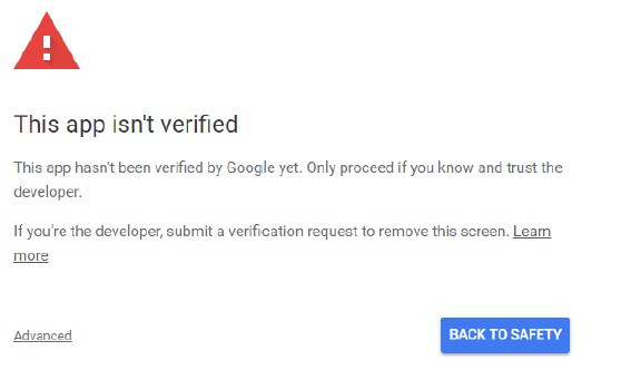
g. Click on the “Advanced” link and then click on the name of the script link. In our case, its “GsScript (unsafe)”.
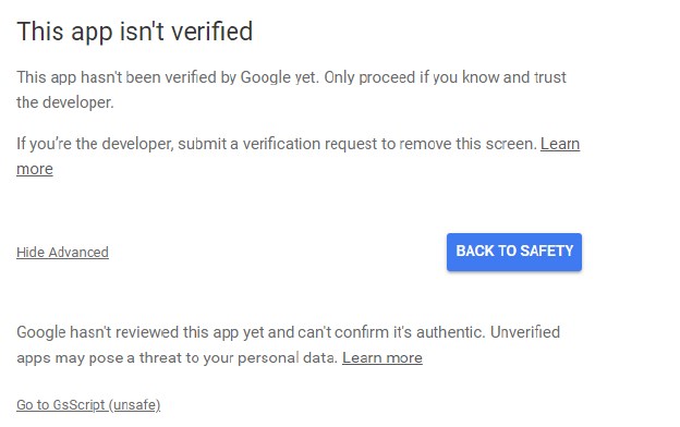
h. The next screen will prompt you to sign in once again into your Google Account. Once done, a permissions prompt will show asking you to allow and trust the script you just wrote.
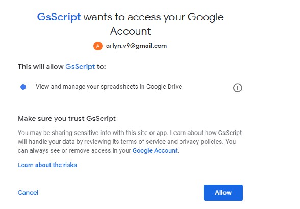
i. Click on the “Allow” button to proceed.
j. Finally, the Deployment is complete. The confirmation screen will appear.
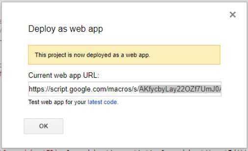
k. Copy the letters appearing between the ‘/s/’ and the ‘/exec’ path segments. This will be used later for configuring the scale. e.g. If the URL looks like this: https://script.google.com/macros/s/AKfycbyGRJaxI5tPGRIw34gYuUO_YOOW7-NfUcg8yb0wt5JIaFKkTxnl/exec
Then only extract this: AKfycbyGRJaxI5tPGRIw34gYuUO_YOOW7-NfUcg8yb0wt5JIaFKkTxnl
l. The above sequence of letters is your Google Spreadsheets Web App ID. To make things easier in the next steps, create a file on your PC called “link.txt” and save this Web ID. Put the file in a USB stick (recommended to use the one that came with your scale), to later import it in the scale.
m. You can find this URL anytime by going to the “Publish” menu item and clicking “Deploy as web app…”.
n. Close the script page and go back to the Google Spreadsheet.
5) Name and Share the Google Spreadsheet
a. Once the Google Spreadsheet has been configured with script code, we need to name it and share it so that the scale can find it and upload data to it.
b. Click the blue “SHARE” Button on the top right corner of the Spreadsheet.
Page | 114
c. The resulting dialog will ask for Sheet name. Just name it anything you want and press OK.
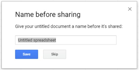
d. The next dialog pop-up shows the “Share with others” parameters. Click on “Get Shareable link” button at the top right of the corner and make sure it turns green. A link appears on dialog. Set the link with “Anyone with the link can edit”. You can also leave it as “…can view”. However, no one will be able to edit the Spreadsheet except you, the owner.
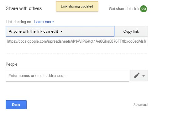
e. Press “Done” to close the dialog.
6) Refresh the Spreadsheet and give it about 5 to 10 seconds until a new menu item appears call “V9 Script”.
7) Click on “V9 Script” -> “Active Log” to activate the data logging script for this sheet.
8) You can add more sheets to the workbook. The scale will only log data on the sheet on which the V9 Script logging has been activated.
33.3.5 Part II: Setup the Arlyn UpScale indicator for Google Spreadsheet Data Logging
Now that you have a Google Spreadsheet loaded with a data logging script, it’s time to setup the Arlyn UpScale indicator to log data onto the spreadsheet.
The scale must be equipped with USB Datalogging Option and either of the TCP/IP options (Ethernet or WiFi). The Google Spreadsheet feature is a subset feature of the USB Data Logging features. The Data logger feature must be set correctly for the Google Spreadsheet feature to work. For further information on setting up USB Data Logging, refer to the USB Data Logging Section.
Follow the steps below to setup Google Spreadsheet datalogging.
Prerequisite: You must have Google Spreadsheets Web App ID as extracted from 6(k) in Section 28.3.1 either saved in a USB stick “link.txt” file or written out.
33.3.5.1 CONFIRM DATA LOGGER SETTINGS
1) In the Arlyn UpScale indicator look for the 3-dot Quick Action menu on the top right corner of the screen and press it. Press the “Settings” option.
2) On the resulting Settings Screen, press the “USB Datalogger” option on the left panel to reveal the Datalogging setup screen.
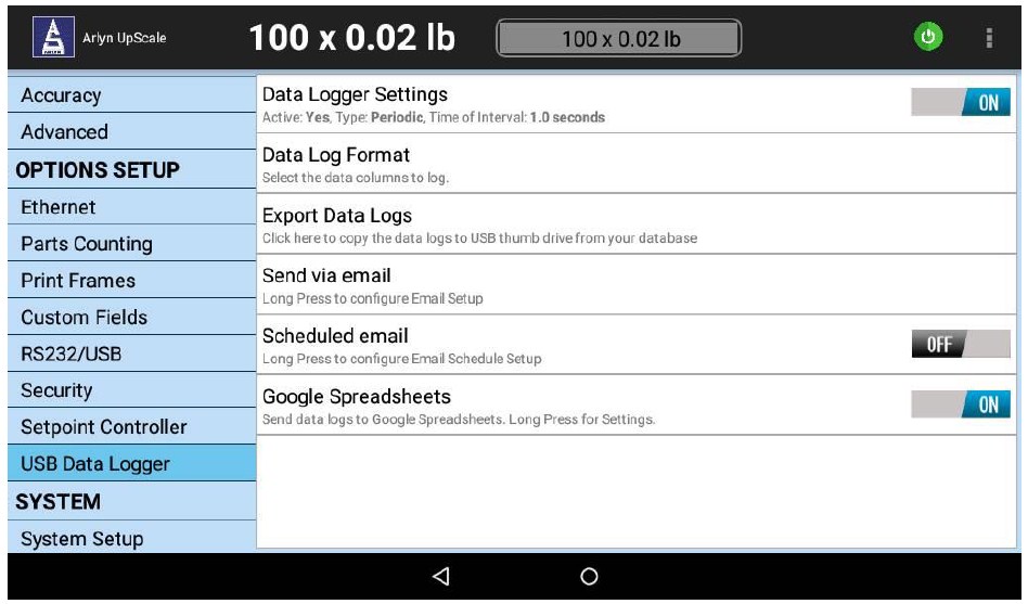
3) Press on “Data Logger Settings” to open the Data Logger Settings dialog.
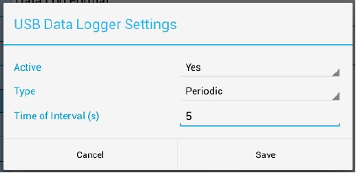
4) Confirm or set the following selections in their respective fields.
Active – Yes
Type – Set the Data Logger mode type to be either Triggered or Periodic. If you set it to Periodic, then the Time Interval field is enabled. You can enter the interval in seconds to set the frequency of logging weights to the internal table.
Time Interval – 10 seconds or more to bypass Google Spreadsheet’s rate limits.
5) Press the SAVE button to save your settings.
33.3.5.2 ENABLE GOOGLE SPREADSHEETS
6) On the same Data Logger Setup Screen, enable Google Spreadsheets by toggling the switch on the option to “ON”.
7) Long Press the Google Spreadsheets option to open up the Google Spreadsheets Web App ID dialog
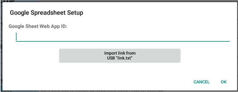
8) There are two ways to assign the Google Spreadsheet Web App ID into the scale.
a. Type in the Web App ID obtained from item (6) (k) in section 28.3.1 into this dialog. This will be hard to do and prone to errors so we do not recommend this method.
b. Or, plug in the USB stick where you saved the “link.txt” file with the Google Spreadsheet Web App ID.
i. Once plugged in, wait for few seconds for the Arlyn UpScale indicator to recognize the USB stick. Then press the “Import link from USB ‘link.txt'” button to import the link.
ii. The new link will appear on the field of the dialog.
9) Press OK to save the Web App ID.
33.3.6 Part III: Start Logging
Once both the computer and Google Spreadsheets have been setup, we can start the logging process. Make sure the that you have enabled “Active Log” on the Google Spreadsheet (see item (7) in Section 27.1).
On the scale on the main weight screen, look for the LOG WEIGHT button (for Triggered setting) or the START LOGGING button (for Periodic setting). Press on it. You will see the data coming into the Spreadsheet live.
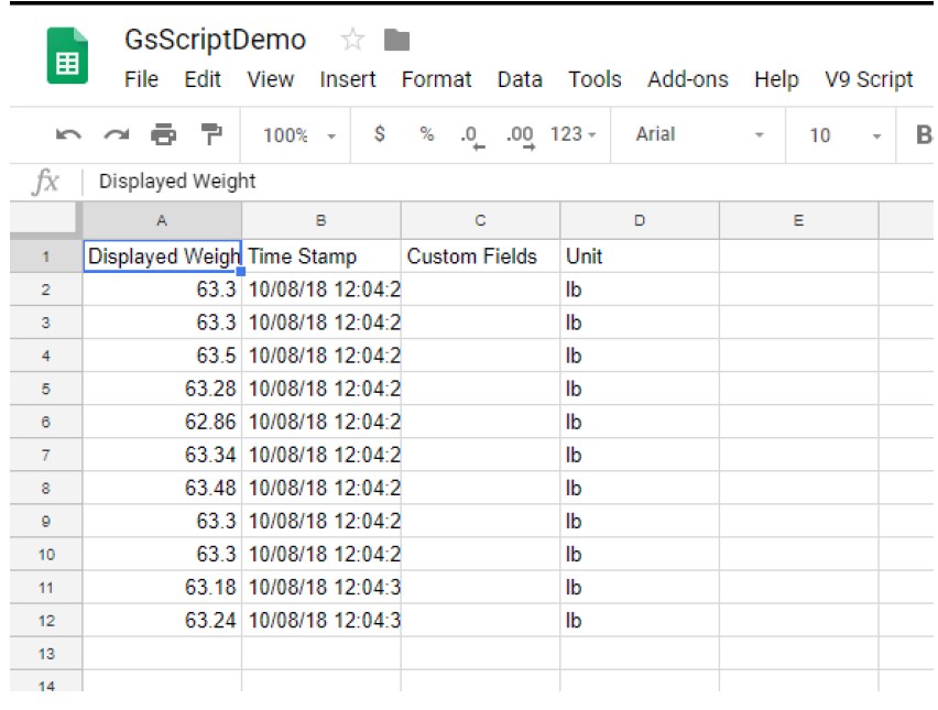
If the order of the columns is not suitable to you, you can easily move the columns around to match your desired order. The Spreadsheet will internally redirect the data to the right column.
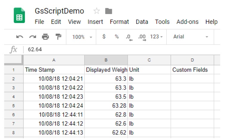
You do not have to have the Spreadsheet open for this feature to work. As long as the scale is connected to the internet, it will log data to the referenced Spreadsheet. You can log in anywhere at any time to view the Spreadsheet.
33.3.7 Technical Support and Disclaimers
The “Data Logging with Google Spreadsheets” feature is available “as is”. We make no warranties as to how it is used and the effects of using this feature on customer’s systems.
Technical support for this and other “Extra Features” will be provided at a nominal charge of $100 an hour.
PART IV
Limited Warranty
34 LIMITED WARRANTY
Arlyn Scales warrants that your Arlyn Scales’ equipment and systems, when properly installed will operate per written specifications. All systems and components are warranted against defects in materials and workmanship for a period of one year.
Arlyn Scales warrants that the equipment sold hereunder will conform to the written specifications authorized by Arlyn Scales.
Arlyn Scales warrants the equipment against faulty workmanship and defective materials. If any equipment fails to conform to these warranties, Arlyn Scales will, at their option, repair or replace such goods returned within the warranty period subject to the following conditions:
- Upon discovery by Buyer of such nonconformity, Arlyn Scales will be given prompt written notice with a detailed explanation of the alleged deficiencies.
- Return Materials Authorization Number (RMA#) must be obtained from Arlyn Scales Technical Support department for any equipment to be returned to Arlyn Scales for warranty replacement or repair. Failure to do so will result in delay for repair or replacement, or could result in equipment lost in shipment, at the expense of the Buyer.
- RMA# must be obtained by calling Arlyn Scales Technical Support at (800) 645-4301 ext. 101.
- Individual electronic components returned to Arlyn Scales for warranty purposes must be packaged to prevent electrostatic discharge (ESD) damage in shipment.
- Examination of such equipment by Arlyn Scales confirms that the nonconformity actually exists, and was not caused by accident, misuse, neglect, alteration, improper installation, improper repair, improper testing or improper return shipping and handling; Arlyn Scales will be the sole judge of all alleged non-conformities.
- Such equipment has not been modified, altered or changed by any person other than Arlyn Scales.
- Arlyn Scales will have reasonable time to repair or replace the defective equipment. The buyer is responsible for shipping both ways.
- In no event will Arlyn Scales be responsible for travel time, or on-location repairs, including assembly or disassembly of equipment, nor will Arlyn Scales be liable for the cost of any repairs made by others.
34.1 Features with Networking (Wi-Fi and Ethernet)
All scales that are manufactured and deployed by ARLYN SCALES, which are equipped with networking capabilities (Ethernet and Wireless) are thoroughly tested and benchmarked before being shipped to customers.
The Ethernet and Wireless devices equipped therein, are shipped with the following factory settings:
- The networking device built in to the scale indicator will be configured to obtain an available IP address from the network in which it is connected, whether it is wired or wireless. It is imperative that the network server, switch or router has DHCP IP Addressing capabilities.
- If the network is secured (e. g. WEP, WPA), then this might impede the device from getting an IP address from the network it is connected to (Wired or Wireless). It is the responsibility of the customer to make sure that the network protocols are set in such a way that there is no problem for the scale to get it’s IP address, even if it means temporarily disabling network security.
- There is no way to access the configuration of the networking device built in the scale without successful IP address assignment. Once the device obtains its IP address, or if it is assigned an IP address by the customer, there is no problem in configuring the networking device, depending on the preference of the customer. The networking devices on these scales support the most popular network security features. It is still the customer’s responsibility to configure the networking device properly so that no problem occurs on any specified function of the scale.
Finally, Arlyn Scales is not responsible for troubleshooting customer’s networking problems arising from integrating the scale on the customer’s network. Arlyn Scales can often provide consulting help with configuration and implementation. This must be separately contracted. The current rate is $100 per hour.
34.2 Premium Features – Technical Support and Disclaimer
The optional capabilities outlined in the “PREMIUM FEATURES” section of this manual is provided “as is”. In that respect, the features maybe incomplete or may have inherent limitations that could hinder the expected basic performance of the scale and/or the feature itself when applied. Arlyn Scales is not responsible for troubleshooting customer’s problems arising from integrating these features on the customer’s systems and/or the scales themselves. Arlyn Scales can often provide consulting help with configuration and implementation without guarantee of expected or positive results. Consultation must be separately contracted. The current rate is $100 per hour.
These features are subject to be removed or changed without notice if Arlyn determines that continuance of these features will negatively affect the performance of its equipment and/or cannot be included due to unforeseen circumstances in hardware/software obsolescence and support.
Arlyn Scales reserves the right to charge a nominal fee for one or all of these premium features when the scale is purchased regardless whether the feature was provided at no cost on previous purchases or type of use of the scale or any other condition.
Arlyn Scales reserves all other rights.
THESE WARRANTIES EXCLUDE ALL OTHER WARRANTIES, EXPRESSED OR IMPLIED, INCLUDING WITHOUT LIMITATION WARRANTIES OF MERCHANTABILITY OR FITNESS FOR A PARTICULAR PURPOSE. ARLYN SCALES WILL NOT, IN ANY EVENT, BE LIABLE FOR INCIDENTAL OR CONSEQUENTIAL DAMAGES.
ARLYN SCALES AND BUYER AGREE THAT ARLYN SCALES SOLE AND EXCLUSIVE LIABILITY HEREUNDER IS LIMITED TO REPAIR OR REPLACEMENT OF SUCH GOODS. IN ACCEPTING THIS WARRANTY, THE BUYER WAIVES ANY AND ALL OTHER CLAIMS TO WARRANTY.
SHOULD THE SELLER BE OTHER THAN ARLYN SCALES, THE BUYER AGREES TO LOOK ONLY TO THE SELLER FOR WARRANTY CLAIMS.
NO TERMS, CONDITIONS OR UNDERSTANDING, OR AGREEMENTS PURPORTING TO MODIFY THE TERMS OF THIS WARRANTY SHALL HAVE ANY LEGAL EFFECT UNLESS MADE IN WRITING AND SIGNED BY A CORPORATE OFFICER OF ARLYN SCALES AND THE BUYER.
WARRANTY TERMS ARE SUBJECT TO CHANGE WITHOUT NOTICE.
35 REVISION HISTORY
| DATE | REVISION | CHANGE |
| 07/17/2017 | V9.0.071717 | – Changed Logo and Address font – Changed overall fonts to conform with other Arlyn Manuals. – Upgraded Menu items to reflect new/modified options in v12 firmware. |
| 01/08/2018 | V9.0.010818 | – Added notes on support for additional Setpoint Definitions. |
| 04/27/2018 | V9.0.042718 | – Added notes about platform legs, Multiplatform considerations and SAW Status screen. |
| 05/30/2018 | V9.0.053018 | – Simplified Span Calibration Section |
| 10/08/2018 | V9.0.100818 | – Added Google Spreadsheet Section – Removed “Optional” from the headings of options due to redundancy – Added Specifications – Added Revision History – Revised Warranty to include Technical Support section for Network and Extra features – Revised Safe Overload in SAW Specifications |
| 10/24/2018 | V9.0.102418 | – Revised Power specifications – Added notation for Google Spreadsheet Web ID import |
| 12/28/2018 | V9.0.122818 | – Added Rate Limit disclaimer to Google Spreadsheet logging |
| 02/25/2019 | V9.0.022519 | – Modified Static IP Configuration for Wireless Connectivity. – Added further warranty terms regarding “Premium Features”. – Re-arranged Import/Export and Setppint Email into Premium Features. |
| 05/10/2019 | V9.0.051019 | – Fixed DHCP configuration on Wireless Connectivity. – Added Section for Barcode features. |
| 10/23/2019 | V9.0.102319 | – Modified SAW Table. |
| 10/14/2020 | V9.0.101420 | – Added Special features section for Setpoint and Data Logging. – Added RS232 pinout diagram. – Added Custom Fields Barcoding section. |
| 11/19/2020 | V9.0.111920 | – Added MODBUS Sections |
