Flow Rate Measurement System – Arlyn UpScale
1 INTRODUCTION
This document serves to describe the flow rate measurement feature of the Arlyn UpScale. It is intended to be used a supplement to the main Arlyn UpScale instruction manual included with the scale. It should not be used as a replacement of the manual.
This supplement assumes that the user of the scale is already familiar with the elements of menus, navigation and various screen indicators in the Arlyn UpScale Touchscreen Indicator.
Setup the scale as described in Chapter 5 of the Instructions Manual before proceeding.
2 FRONT PANEL VIEW
2.1 Regular Scale View
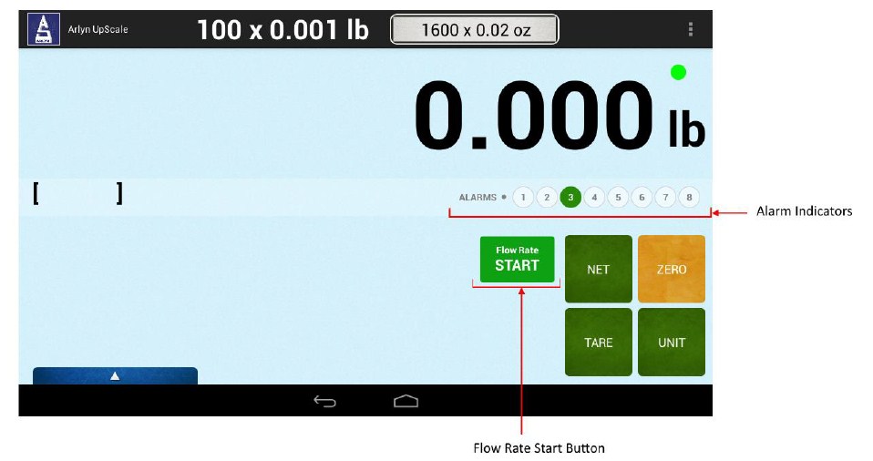
FLOW RATE START BUTTON – Press this button to begin Flow Rate calculation.
ALARM INDICATORS – Setpoint triggers for any alarms that might occur during the regular weighing process. These can be set in the Flow Rate Setup Screen.
ALARMS – NON-FLOW RATE OPERATION
High Weight Alarm (Pin 2) [Default: Turns on at 100lbs]
Low Weight Alarm (Pin 3) [Default: Turns on at 0lbs]
2.2 Flow Rate View
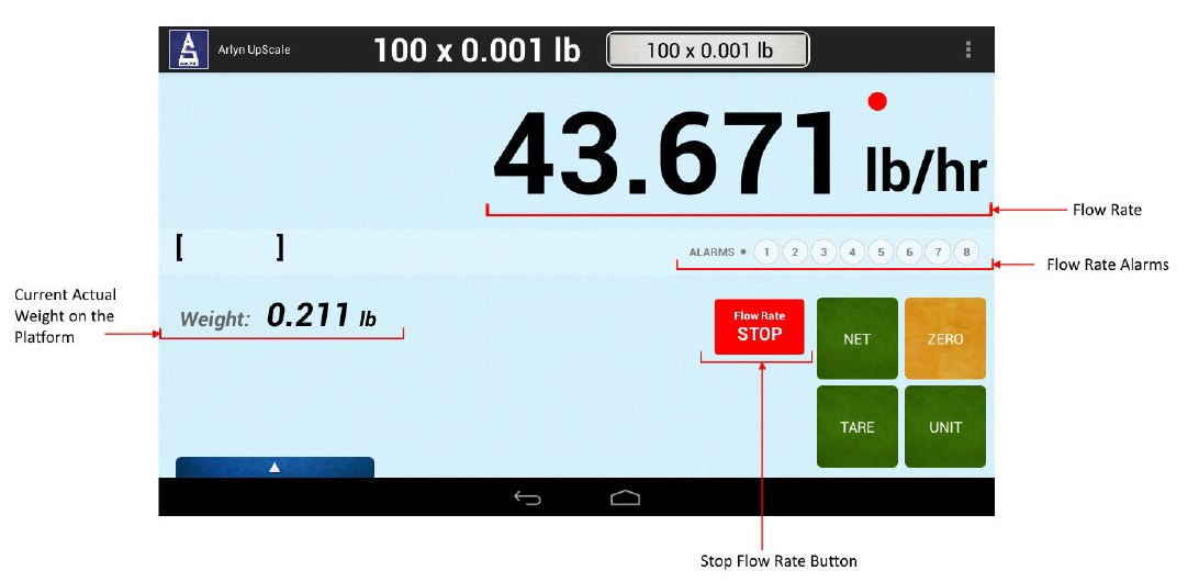
FLOW RATE – Shows the current calculated flow rate
FLOW RATE ALARMS – Setpoint triggers that shows any alarms occurring during the Flow Rate process.
STOP FLOW RATE BUTTON – Press this button to stop the Flow Rate calculation.
CURRENT ACTUAL WEIGHT – Shows the actual weight on the platform.
ALARMS – FLOW RATE OPERATION
Pin 1 – No Flow Alarm [Default: Turns on when Flow Rate < 1.0 gal/hour for 30s]
Pin 2 – High Weight Alarm [Default: Turns on when weight is >= 100lb]
Pin 3 – Low Weight Alarm [Default: Turns on when weight is <= 0lb]
3 FLOW RATE MEASUREMENT SYSTEMW
The Flow Rate Measurement System is a feature that allows the user to measure the flow rate of liquid dispensed from a container based on the change in weight of that container.
The system operates based on specialized built-in configurations specifically designed for flow rate measurement. The measurement system uses a combination of accurate weight measurements, filtering, setpoint control, analog output and optional data logging to bring about a complete application implementation.
To activate flow rate calculation, simply press the Flow Rate Start Button on the front panel.
4 THEORY OF OPERATION
4.1 Flow Rate Calculation
When the flow rate calculation system is activated on the scale, depending on the actual flow rate of the liquid from the drum, the scale may not show the flow rate value immediately after activation. This is because the scale has a certain resolution and the flow of liquid needs to surpass this resolution.
For example, let’s assume a regular scale capacity of 1500lbs with a resolution of 0.2lbs. This means that if the container on the platform (a drum) has not dispensed at least 0.2lbs of the liquid, the next flow r
Taking this principle into consideration, let’s say that liquid of specific gravity 1.0 is dispensed from the drum at a flow rate of 1.0gal/hr. This means that for the specific gravity, the flow rate is 8.3lbs/hour ˜ 0.1 lbs./minute.
Using the above specification, the next flow rate calculation to appear on screen will take at least 2 minutes. (0.1 x 2 min = 0.2lbs drop in weight).
In addition to this method of calculation, the system is designed to produce the most accurate result after 0.6lb drop in weight. Therefore, when activating the flow rate calculation for the first time, the screen shows the indicator ‘P’ at the bottom of the screen, notifying the user that the next few values shown on screen are preliminary and should not be taken into consideration. These values will only change after a 0.2lb drop in weight has occurred.
The ‘P’ indicator will disappear once a 0.6lb drop in weight is detected. For a liquid of specific gravity 1.000 and a flow rate of 1.0 gal/hour, this can take up to 6 minutes.
If the platform resides on a vibrating surface, or if the user shakes the platform in anyway, the flow rate calculation will be affected. The discrepancies in values may last for a few minutes (especially if the flow rate is very low) before the system stabilizes with accurate flow rate values. Precautions need to be taken so that such events should not happen if accuracy is desired at all times. If this characteristic is not desired, you can activate “Super Stable Flow Rate” feature as described in Section 4.3 below or in Flow Rate Averaging Parameters (Section 5.2)
For fast flow rates, new values will be calculated every 3 seconds even if the drum scale is dispensing more than 0.2lbs/second. The correction time for fast flow rates is negligible.
Now if the scale has a lower resolution, then the calculation of flow rate takes a shorter time. For example, if the scale has a resolution of 0.001lb, this means that to calculate the next flow rate value should take less than a second. It all depends on the resolution of the scale and its capacity.
4.2 “No Flow” Alarm
In order to use the scale’s “no flow” alarm signal the scale must measure a flow rate of at least 1 gallon per hour if the liquid’s specific gravity is 1. An alarm will signal if the system detects that the flow is less than 1 gallon per hour notifying the user that the liquid is not being fed through the pump.
This is the minimum flow rate condition for this particular specific gravity. If the “no flow” alarm is set to a higher flow rate (using the Flow Rate Alarm Settings (Section 5.3) setup screen), then the alarm will signal if the flow rate falls below that set rate. If the “no flow” alarm is set to a higher flow rate, then the alarm will signal within a shorter time compared to the above specification. This time depends on how long it takes to dispense the weight of the liquid that is three times the resolution of the scale.
Example, for 1500lb scale with a resolution of 0.2lbs, for a liquid of SG = 1 flowing at 1 gallon per hour, it will take 6 minutes for the container to dispense 0.6lbs of weight. If the “no flow” alarm was set at this minimum level, then the alarm will signal in 6 minutes for a “no flow” condition.
If the “no flow” alarm was set at 2 gallons per hour, then parameters for the alarm signal will change. For this case, assume that the liquid was flowing at 2 gallons per hour; this means the container dispenses 0.6lbs of weight in 3 minutes. Therefore, if the flow rate falls below this level for 3 minutes, the “no flow” alarm will signal. The higher the flow rate set in the “No Flow” alarm screen, the shorter the time it takes for the alarm to signal in the “no flow” condition
4.3 Super Stable Flow Rate
If you require that the scale shows extremely stable readings of Flow Rate despite of vibrations and other external disturbances, you can activate Super Stable Flow Rate feature. This will keep the flow rate reading stable at the expense of speed (at which the flow rate changes). It is only recommended to use this feature if the environment this apparatus will operate on is extremely unstable with a lot of vibrations and other noisy elements.
5 FLOW RATE SETUP
Now that we understand how this scale calculates flow rate, we will now learn how to set the parameters for Flow Rate so you can get accurate readings for your liquid flow.
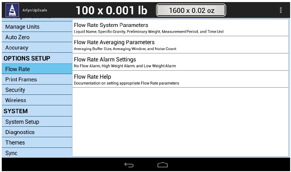
The Flow Rate setup screen can be accessed through MENU/SETTINGS/FLOW RATE. In this menu, there are two options:
- Flow Rate System Parameters
- Flow Rate Averaging Parameters
- Flow Rate Alarm Settings
5.1 Flow Rate System Parameters
The Flow Rate System Parameter Settings is used to set the specifications of the Flow Rate Measurement system. This includes settings such as Specific Gravity of the liquid, the preliminary weight of flow, the measurement period between two weight values and per time unit.
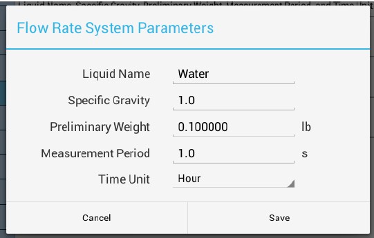
Liquid Name
This field is optional. It allows you to set what the name of the liquid in the container of your flow rate apparatus.
Specific Gravity
The Specific Gravity of the liquid in your flow rate apparatus.
Preliminary Weight
This is the initial weight that has to flow out before the Flow Rate system starts measuring flow rate. If this weight has not flowed out yet, the system will show “P” on the front panel.
Measurement Period
This is the period of time to between measuring two weight values to calculate Flow Rate.
Time Unit
This is the division of time for Flow Rate.
5.1.1 Notes on Specific Gravity
The specific gravity of a liquid is defined as the ratio of the density of a given solid or liquid substance to the density of water at a specific temperature and pressure, typically at 4°C (39°F) and 1 atm (760.00 mmHg). It is, by definition, a dimensionless quantity.
Mathematically, specific gravity (SG) is expressed as:
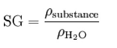
where Psubstance is the density of the substance, and ph3o is the density of water. (Source: Wikipedia)
For example, the SG of water is 1.000. The SG of Hexene is 0.673.
In the Flow Rate System, the specific gravity is used to display the weight of the liquid in gallons. Press the UNIT button to change the units to Gallons (or any other desired unit).
5.2 Flow Rate Averaging Parameters
The Flow Rate Averaging parameters are used to set the filter values for the Flow Rate Measurement system. The system uses these values to calculate the most accurate results at the time of operation. Keep these settings as they are unless it is absolutely necessary to change them.
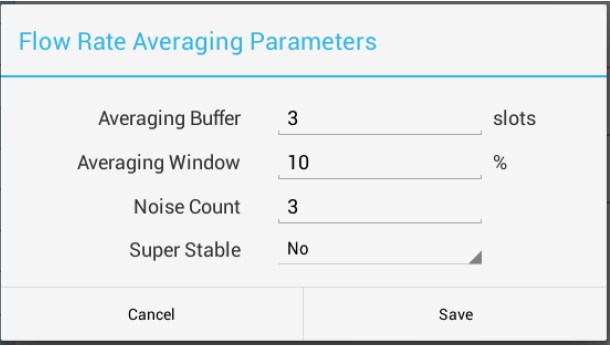
5.2.1 Averaging Buffer
This is the buffer that is used to average each calculation of flow rate to give out a value that is gradually calculated over time as the flow of the liquid continues. It is recommended that the user should not change the default value of this parameter.
Assigning a bigger number to this value increases the number of slots the system provides to the flow rate averaging routine. This gives out more accurate results. The drawback is a slowdown in performance as the number of slots increases.
5.2.2 Average Percentage Window
The average percentage window is the parameter used to detect values that will renew the averaging buffer. The factory default is 10.00% of the current calculated flow rate. This means that if the flow rate wavers above this window for at least 3 instances of calculation, then it is considered to be the new flow rate value. The flow rate averaging buffer (discussed above) is flushed and initialized with the new flow rate value.
Increasing the percentage value on this parameter increases the stability of the calculated flow rate value, but decreases its accuracy. maximum number of slots that can be used is 100.
5.2.3 Noise Count
This is the noise count of filtering mechanism. This sets the number of weight values that need to be discarded before considering that the new weight value is a new value and not part of the current weight value averaging process. The noise count is inversely proportional to weight accuracy and directly proportional to performance. This means that the higher this number, the less accurate the weight value, the faster your performance.
5.2.4 Super Stable
If you require that the scale shows extremely stable readings of Flow Rate despite of vibrations and other external disturbances, you can activate Super Stable Flow Rate feature. This will keep the flow rate reading stable at the expense of speed (at which the flow rate changes). It is only recommended to use this feature if the environment this apparatus will operate on is extremely unstable with a lot of vibrations and other noisy elements.
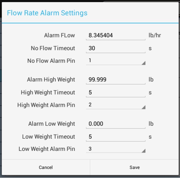
5.3 Flow Rate Alarm Settings
The Flow Rate Alarm Settings parameters are used by the Flow Rate Measuring system to determine any instances at which the Flow Rate measurement is being done improperly. This includes alarms for low or no flow alarm (Alarm Flow), too much liquid in the drum (High Weight Alarm), and not enough liquid (Low Weight Alarm).
5.3.1 “No Flow” Alarm
This set of parameters helps determine the conditions at which the system will trigger a “No Flow Alarm”
5.3.1.1 Alarm Flow
The Alarm Flow Rate is the minimum flow rate at which the system will not go into “No Flow” Alarm. If the flow rate falls below this value, the system will produce a “No Flow” alarm at the specified output.
The minimum flow rate is set to a factory default of 8.3 lb/hr. This value corresponds to a flow rate of 1 gallon of water per hour. Any value set below this threshold is invalid no matter what the specific gravity is specified to be. However, the user may set values above this minimum value without limitations.
Notice that the minimum flow rate displayed in gallons/hour will reflect the specific gravity specified in the setup screen. For example, if the liquid has a specific gravity of 1, the minimum flow rate displayed will show 1 gal/hr. If the specific gravity of the liquid is 0.673 (Hexene), then the minimum flow rate will displayed will be 1.5 gal/hr. Consequently, the user cannot set the minimum flow rate below the one specified in gallons per hour. The minimum flow rate in gallons per hour will always correspond to a flow rate of 8.3 lb/hr.
5.3.1.2 No Flow Alarm Timeout
This alarm is a timeout specification that notifies the user when there is zero flow from the system. This is a forced timeout that is independent from the “No Flow” Alarm feature described earlier.
If the Flow Rate calculation has been activated and there is no actual flow of liquids, then the “No Flow Timeout” Alarm will go off at the specified time by the user. This feature uses the same alarm voltage outputs as the “No Flow” alarm voltage outputs.
5.3.1.3 No Flow Alarm Pin
The “No Flow” Alarm Pin is the output that will be triggered when a “No Flow” alarm has occurred. This can be set to one specific output. By default, this is set to Setpoint Output #1. For reference on Setpoint outputs, see Section 16.7 of the Instruction Manual, or take a look at a snapshot of output connector diagram in Section 5.4
5.3.2 High Weight Alarm
This set of parameters helps determine the conditions at which the system will trigger a “High Weight Alarm”
The scale will trigger a designated output for high weight alarms if the weight specified in this field is reached. By default, the high weight alarm output is set to Setpoint Output #2.
The definitions for High Weight Timeout and High Weight Alarm Pin are similar to the No Flow parameters described above in Section 5.3.1.
5.3.3 Low Weight Alarm
This set of parameters helps determine the conditions at which the system will trigger a “Low Weight Alarm”
The scale will trigger a designated output for low weight alarms if the weight specified in this field is reached. By default, the low weight alarm output is set to Setpoint Output #3.
The definitions for Low Weight Timeout and Low Weight Alarm Pin are similar to the No Flow parameters described above in Section 5.3.1.
5.3.4 Notes on Low and High Weight Alarms
Both the Low weight and high weight values specified in the Flow Rate System Setup are responsive to the gallons unit just like the “No Flow” alarm value. Consequently, the gallons specified in these fields are dependent on the specific gravity value specified here.
5.4 Alarm Output Connector and Pin Diagram
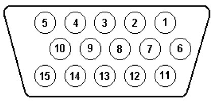
| SETPOINT | PIN |
| 1 | 8 |
| 2 | 7 |
| 3 | 6 |
| 4 | 11 |
| 5 | 12 |
| 6 | 13 |
| 7 | 14 |
| 8 | 15 |
| POWER (3.3VDC) | 10 |
| GND | 9 |
6 DATA OUTPUT
The current Flow Rate being measured on the scale can be sent out to any optional available digital output such as RS232, USB, Ethernet or Wi-Fi Terminal/Socket.
For more detailed description on how to utilize these outputs, please refer to the Arlyn UpScale User Manual available on Arlyn Scales website in the Product Manuals and Specification Sheets page.
6.1 Flow Rate Data Frame
The following is the output frame from the scale when Flow Rate is activated.
[DATE] [TIME] [GROSS WEIGHT] [UNIT] [NET WEIGHT] [UNIT] [FLOW RATE] [FLOW RATE UNIT]
Example:
05/30/2018 15:32:31 25.761 lb 10.761 lb 1.000 lb/hr
6.2 Data Output Methods
The data can either be queried by sending a command to the scale or the data can be streamed out at a defined period or by pressing the PRINT key on the scale.
To retrieve the data from the scale, the command is “~*P*~” without quotes. For more information on types of commands to be sent, refer to Page 9 of the Arlyn UpScale User Manual.
7 LIMITED WARRANTY
Arlyn Scales warrants that your Arlyn Scales equipment and systems, when properly installed will operate per written specifications. All systems and components are warranted against defects in materials and workmanship for a period of one year.
Arlyn Scales warrants that the equipment sold hereunder will conform to the written specifications authorized by Arlyn Scales. Arlyn Scales warrants the equipment against faulty workmanship and defective materials. If any equipment fails to conform to these warranties, Arlyn Scales will, at their option, repair or replace such goods returned within the warranty period subject to the following conditions:
- Upon discovery by Buyer of such nonconformity, Arlyn Scales will be given prompt written notice with a detailed explanation of the alleged deficiencies.
- Return Materials Authorization Number (RMA#) must be obtained from Arlyn Scales Technical Support department for any equipment to be returned to Arlyn Scales for warranty replacement or repair. Failure to do so will result in delay for repair or replacement, or could result in equipment lost in shipment, at the expense of the Buyer.
- RMA# must be obtained by calling Arlyn Scales Technical Support at (800) 645-4301 ext. 101.
- Individual electronic components returned to Arlyn Scales for warranty purposes must be packaged to prevent electrostatic discharge (ESD) damage in shipment.
- Examination of such equipment by Arlyn Scales confirms that the nonconformity actually exists, and was not caused by accident, misuse, neglect, alteration, improper installation, improper repair or improper testing; Arlyn Scales will be the sole judge of all alleged non-conformities.
- Such equipment has not been modified, altered or changed by any person other than Arlyn Scales.
- Arlyn Scales will have reasonable time to repair or replace the defective equipment. The buyer is responsible for shipping both ways.
- In no event will Arlyn Scales be responsible for travel time, or on-location repairs, including assembly or disassembly of equipment, nor will Arlyn Scales be liable for the cost of any repairs made by others.
THESE WARRANTIES EXCLUDE ALL OTHER WARRANTIES, EXPRESSED OR IMPLIED, INCLUDING WITHOUT LIMITATION WARRANTIES OF MERCHANTABILITY OR FITNESS FOR A PARTICULAR PURPOSE. ARLYN SCALES WILL NOT, IN ANY EVENT, BE LIABLE FOR INCIDENTAL OR CONSEQUENTIAL DAMAGES.
ARLYN SCALES AND BUYER AGREE THAT ARLYN SCALES SOLE AND EXCLUSIVE LIABILITY HEREUNDER IS LIMITED TO REPAIR OR REPLACEMENT OF SUCH GOODS. IN ACCEPTING THIS WARRANTY, THE BUYER WAIVES ANY AND ALL OTHER CLAIMS TO WARRANTY.
SHOULD THE SELLER BE OTHER THAN ARLYN SCALES, THE BUYER AGREES TO LOOK ONLY TO THE SELLER FOR WARRANTY CLAIMS.
NO TERMS, CONDITIONS OR UNDERSTANDING, OR AGREEMENTS PURPORTING TO MODIFY THE TERMS OF THIS WARRANTY SHALL HAVE ANY LEGAL EFFECT UNLESS MADE IN WRITING AND SIGNED BY A CORPORATE OFFICER OF ARLYN SCALES AND THE BUYER.
