3-Wire Cylinder Scales 0-5VDC – Line Powered
[DOWNLOAD PDF]
620G Cylinder Scales Line Powered 0-5VDC Output – Wiring Diagram
Diagram below illustrates wiring diagram for 620G Cylinder Scales equipped with Line Powered 0-5VDC (3-Wire) and no display.
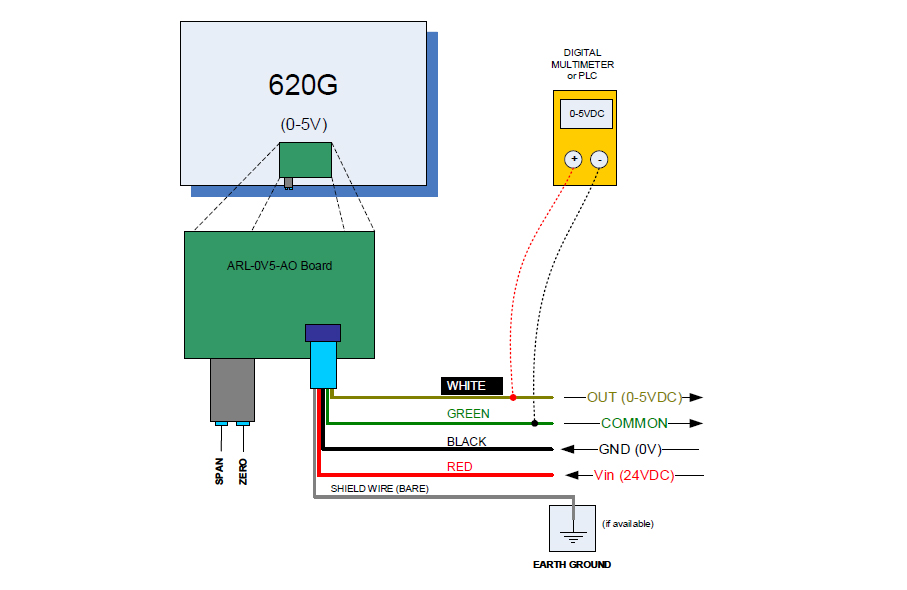
To check the output:
- Connect the RED wire to a 24V DC outlet.
- Connect the BLACK wire to GROUND.
- You will now have 0-5VDC output coming from the WHITE wire with reference to COMMON (GREEN wire)
- Use a Voltmeter or a digital multimeter to check the voltage on the WHITE wire. Connect the multimeter as shown.
- Press the platform to see the deflection in current.
- Use the SPAN and ZERO potentiometers located on the side of the board to calibrate your platform current output.
- Connect the GROUNDING WIRE (bare) to a suitable Earth Ground location in your building.
Refer to enclosed calibration document on how to use the span and zero trimmers to calibrate your scale (if needed)
