2-Wire Cylinder Scales 4-20mA – Loop Powered
[DOWNLOAD PDF]
620G Cylinder Scales 4-20mA (2-Wire) Wiring Diagram (Loop Powered)
Diagram below illustrates wiring diagram for 620G Cylinder Scales equipped with Loop Powered 4-20mA (2-Wire) and no display.
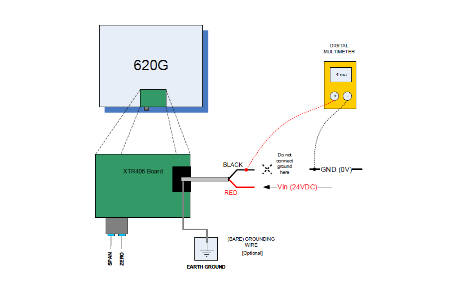
To check the output:
- Connect the RED wire to a 24V DC outlet.
- Connect the GROUNDING WIRE (bare) to a suitable Earth Ground location in your building. This is optional. This will help determine faults in the scale if any and increase stability of your readings.
- Connect the BLACK wire to the input terminal (+) of the ammeter or digital multimeter.
- Connect the return terminal (-) or “common” of the ammeter to ground.
- You will now have 4-20 mA reading from the ammeter.
- Press the platform to see the deflection in current.
- Use the SPAN and ZERO potentiometers located on the side of the board to calibrate your platform current output.
